Motivation

This is my extended version of the Trapezoid VCO core designed by Don Tillman. My first implementation for a 15V banana system with separate waveshaper can be found here. My second implementation for a 15V banana system with integrated waveshaper can be found here.This time I moved on to the 12V Eurorack format. The core is still based on the original design from Don (used with permission). I found the original article and schematic about the Trapezoid VCO on Don Tillman's site (Link to original article from 19 July 2003). The article consists off three parts with the core implementation in part 2. I kept the basic idea and changed nearly everything else. I use an other exponentiator scheme and temperature stabilization. Another reference voltage device is used. A octave switch is added. And quadrature square outputs are implemented. As well as the additional waveforms triangle, sine, ramp up, ramp down and pulse.
For the extended Version I added the two missing outputs for ramp up, ramp down and pulse. Now this VCO has all the usual wave outputs, all 90deg apart.
Specs and features
- Trapezoid quadrature output
- Square quadrature output
- Triangle quadrature output
- Sine quadrature output
- Pulse output, 0deg, 90deg, 180deg, 270deg
- Ramp up output 0deg, 90deg, 180deg, 270deg
- Ramp down output 0deg, 90deg, 180deg, 270deg
- Octave switch
- Through zero modulation
- PWM input for 0deg, 90deg, 180deg, 270deg pulse
- V/Oct, FM log and trough zero CV input
- Temperature compensated
- Fine frequency setting
- Runs on +/-15V and +/-12V
- Power consumption around 150mA each rail
Implementation
Schematic

Trapezoid VCO schematic: Control board 01

Trapezoid VCO schematic: Control board 02

Trapezoid VCO schematic: Control board 03

Trapezoid VCO schematic: Main board one 01

Trapezoid VCO schematic: Main board one 02

Trapezoid VCO schematic: Main board one 03

Trapezoid VCO schematic: Main board two 01

Trapezoid VCO schematic: Main board two 02
Description:
J. Donald Tillman did an excellent job describing the core of his Trapezoid VCO. Please refer to the original article as linked above. Don Tillman gave me the advice to use only two capacitors in the core. The exponentiator I use is a well known and a classical design. You can find many description of it out there. The rest is straight forward.
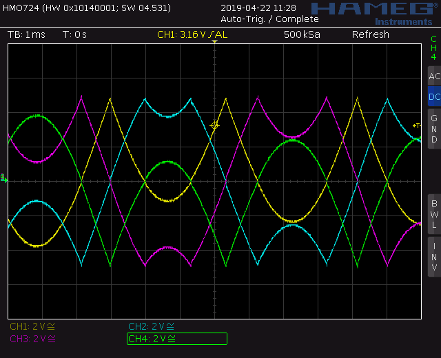
Trapezoid VCO screenshot: Trapezoid quadrature waveforms
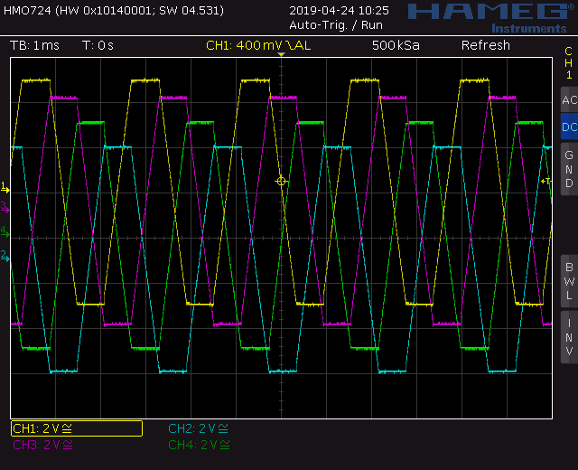
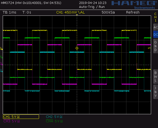
The quadrature, square and ramp waveforms are offset on the scope for better visibility
Trapezoid VCO screenshot: Square quadrature waveforms
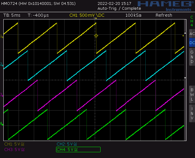
Trapezoid VCO screenshot: Ramp up
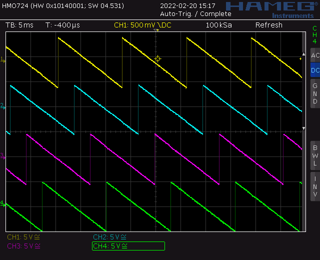
Trapezoid VCO screenshot: Ramp down
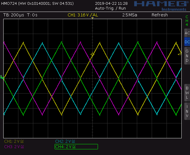
Trapezoid VCO screenshot: Triangle quadrature waveforms
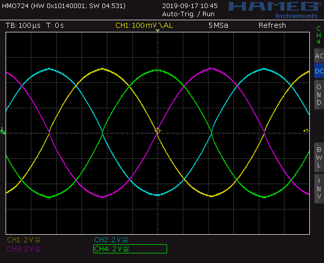
Trapezoid VCO screenshot: Sine quadrature waveforms
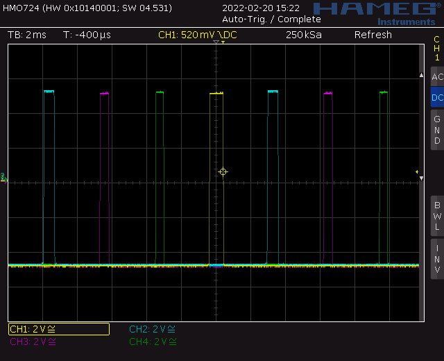
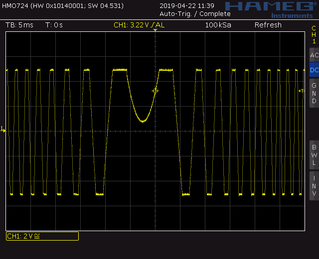
Trapezoid VCO screenshot: Pulse waveforms
Trapezoid VCO screenshot: Through zero modulation
Trapezoid VCO screenshot: Through zero modulation
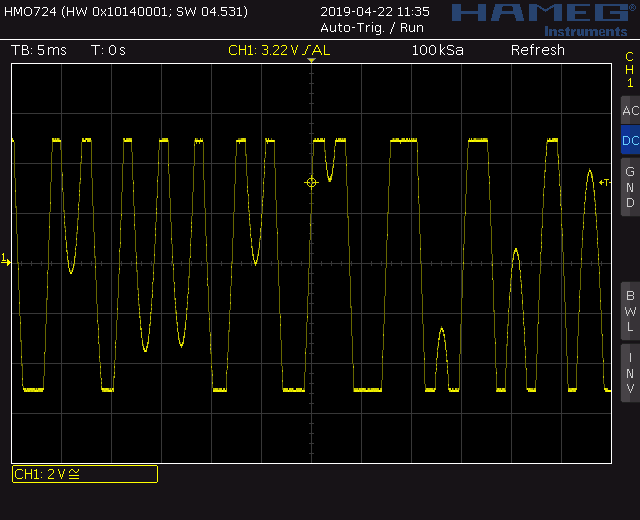
Trapezoid VCO screenshot: Through zero modulation
Top
Calibration
- First make a gross test. You should have a signal at every output, pots and inputs reacting.
- Initial frequency
- Set P1 (TZ) to min (off).
- Set octave switch to 1 (lowest).
- Set P2 (fine frequency) to center.
- Adjust TR_1 (control PCB) to 20Hz.
- OTA offset voltage
- Remove DG409
- Ground the V/Oct input
- Set P1 (TZ) to max.
- Set octave switch to 5.
- Set P2 (fine frequency) to center.
- Set P4 (FM log) to zero
- Set P3 (TZ mod) to zero
- Measure the DC offset at MP_1 on the backside (pin 13 of the IC3OTA1). Adjust trimmer TR1 (main PCB 01) to zero volt.
- Measure the DC offset at MP_2 on the backside (pin 12 of the IC3OTA2). Adjust trimmer TR2 (main PCB 01) to zero volt.
- Don't forget to put the DG409 back in
- V/Oct adjust
- Low frequency: Set the frequency to about 100Hz
- Apply +1V to the V/OCT input (Use precision voltage source or keyboard). The frequency should double
- Adjust Trimmer TR_3 (control PCB) to until it works.
- High frequency: Set the frequency to about 2500Hz
- Apply +1V to the V/OCT input (Use precision voltage source or keyboard). The frequency should double
- Adjust Trimmer TR_2 (control PCB) to until it works.
- Repeat low and high frequency trim.
- A more elaborate procedure is found here: NGF: VCO Core two
- Sine adjust
- Connect an oscilloscope to the 0deg (90deg) sine output.
- Adjust TR_3 (TR_5) on the main PCB 01 until the triangle rounds nicely to a sine. TR_4 (TR_6) adjusts the DC offset.
- Start with TR_3 (TR_5) and then adjust TR_4 (TR_6).
- Those adjustments are not independent. Go back and forth until you are satisfied.
- Ramp adjust
- Connect an oscilloscope to the 0deg (90deg, 180deg, 270deg) ramp output.
- Adjust TR_1 (TR_3, TR_5, TR_7) and TR_2 (TR_4, TR_6, TR_8) (main PCB 02) until the ramp looks like a straight line
- Square offset
- Connect an oscilloscope to the 0deg (90deg) square output.
- Adjust TR_7 (TR_10) (main PCB 01) for zero offset.
- Pulse output level
- Connect an oscilloscope to the 0deg (90deg, 180deg, 270deg) pulse output.
- Adjust TR_8 (TR_9, TR_11, TR_12) (main PCB 01) for the desired output level (5Vpp).
Building hints
- R10 (2k tempco 3300ppm) is mounted beneath the SSM2220
- Match C2 and C3 (Main PCB
Special parts
- The SSM2220 could be replaced with two (hand) matched transistors
- The OTA CA3280 could be replaced with the AS3280 (not tested though).
Download
Trapezoid extended VCO control board documentation downloadTrapezoid extended VCO control board Gerber files download
Trapezoid extended VCO main board 01 documentation download
Trapezoid extended VCO main board 01 Gerber files download
Trapezoid extended VCO main board 02 documentation download
Trapezoid extended VCO main board 02 Gerber files download
Trapezoid extended VCO *.fpd file
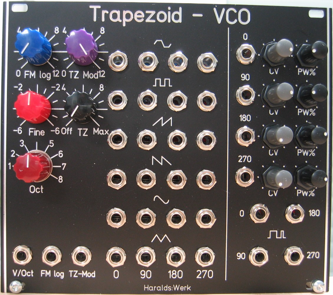
Trapezoid extended VCO: Front view
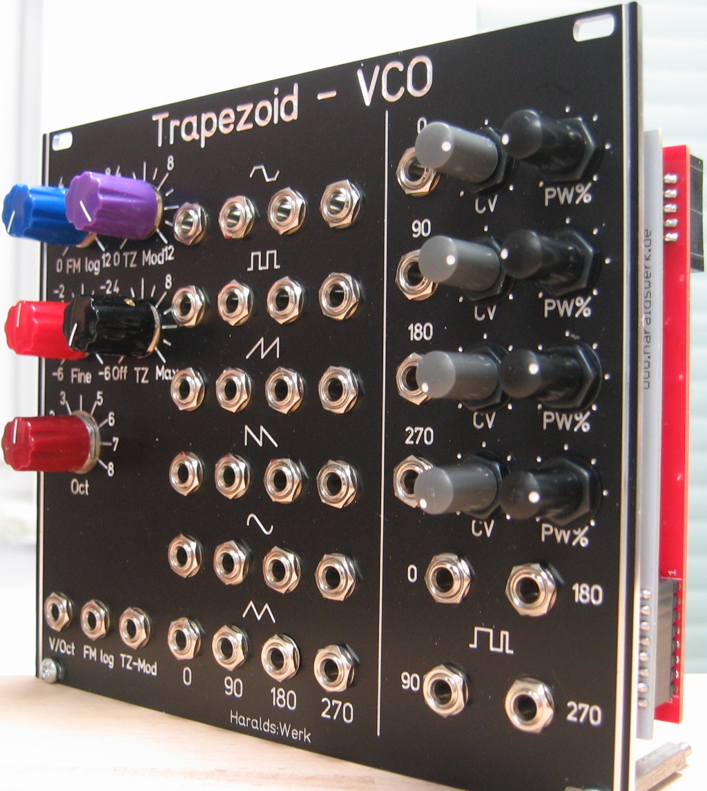
Trapezoid extended VCO: Front view
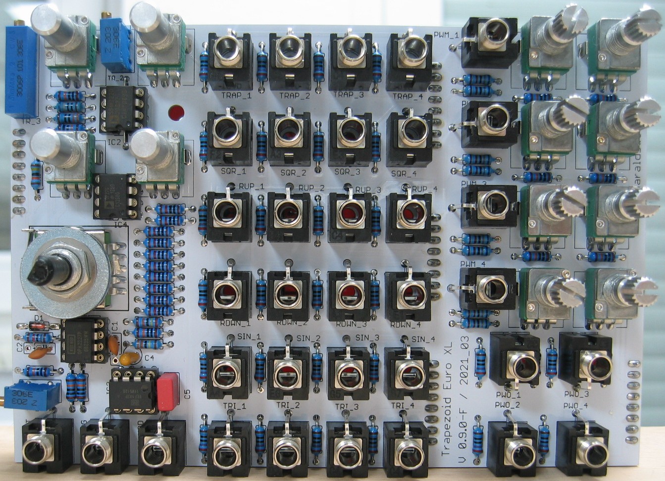
Trapezoid extended VCO: Populated control PCB
Trapezoid extended VCO: Populated main PCB 01
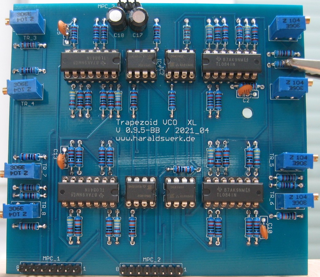
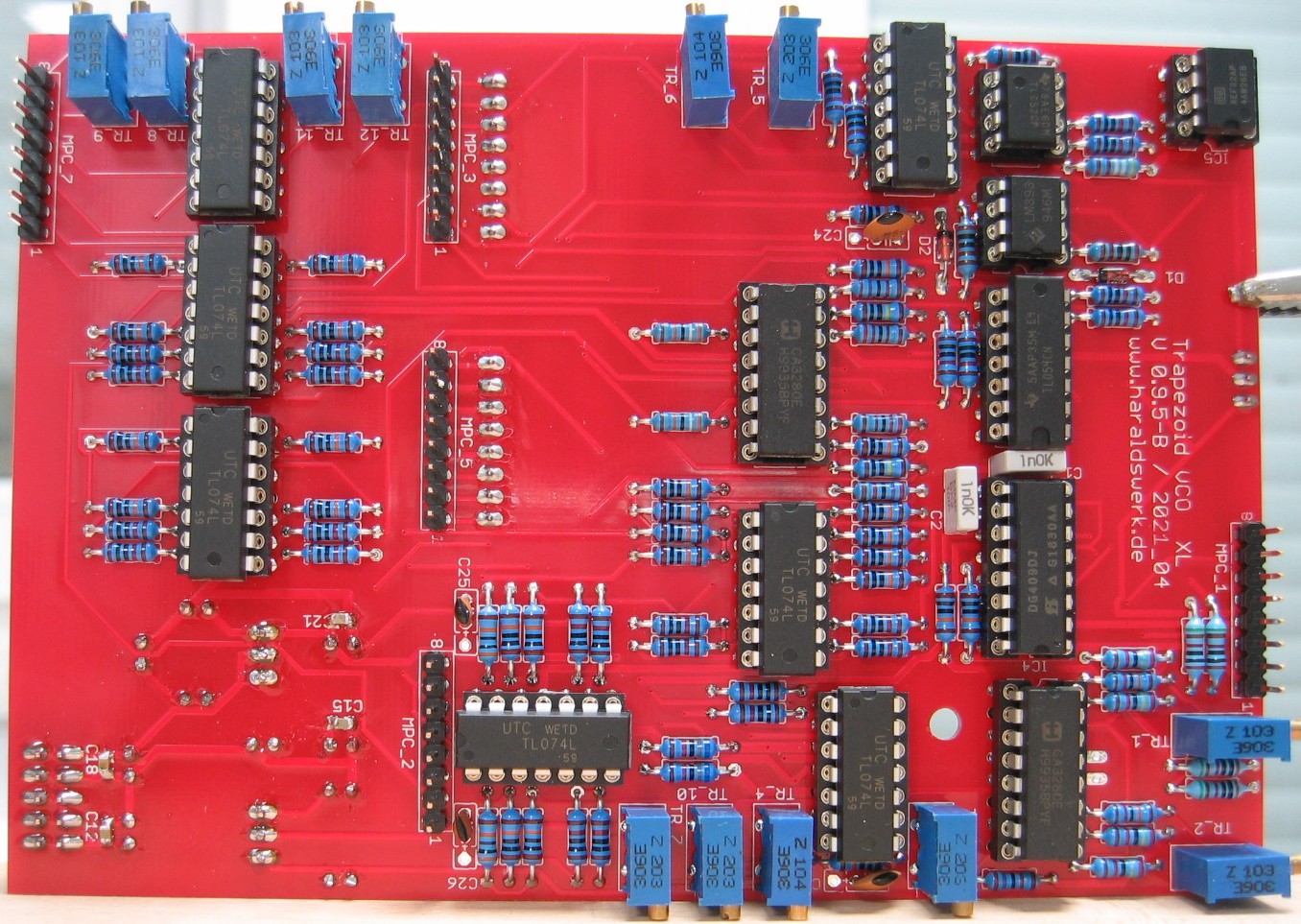
Trapezoid extended VCO: Populated main PCB 02
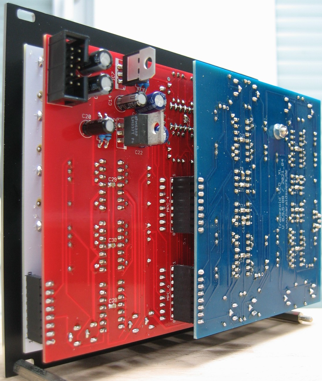
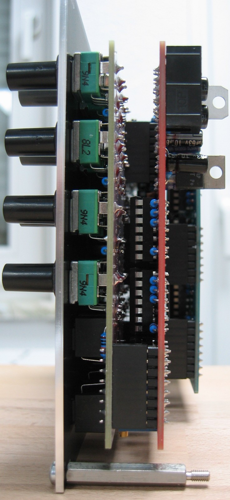
Trapezoid extended VCO: Back view