Motivation

I always wanted a VCO with through zero capacity. Why not combining this with a unusual wave form and quadrature outputs? Usable as LFO as well? I found the original article and schematic about the Trapezoid VCO on Don Tillman's site (Link to original article from 19 July 2003). The article consists off three parts with the core implementation in part 2. I kept the basic idea and changed nearly everything else. I use an other exponentiator scheme and temperature stabilization. A LFO option is added. Another reference voltage device is used. And quadrature square outputs are implemented. The additional waveforms triangle, sine, ramp up, ramp down and pulse are covered in an extra module.
Updated to V 2.2.0. With help from Don Tillman I could simplify the schematic and switched to two capacitor design. Thanks Don.
Specs and features
- Trapezoid quadrature output
- Square quadrature output
- Through zero modulation
- V/Oct, FM log and trough zero CV input
- Temperature compensated
- LFO Range switch
- Coarse and fine frequency setting
- Runs on +/-15V and +/-12V
- Power consumption around 65mA each rail
Implementation
Schematic

Trapezoid VCO schematic
Description:
J. Donald Tillman did an excellent job describing the core of his Trapezoid VCO. Please refer to the original article as linked above. Don Tillman gave me the advice to use only two capacitors in the core. The exponentiator I use is a well known and classical design. You can find many description of it out there. The rest is straight forward. The LFO option is implemented with the DG202. Here are just two capacitors added switchable in parallel to the audio frequency capacitors. The connectors shown are for adding the waveform module to generate triangle, sine, ramp up, ramp down and pulse.
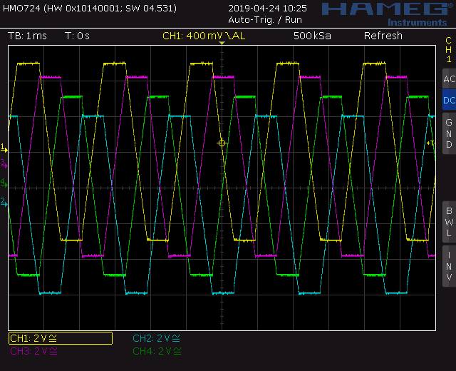
Trapezoid VCO screenshot: Trapezoid quadrature waveforms
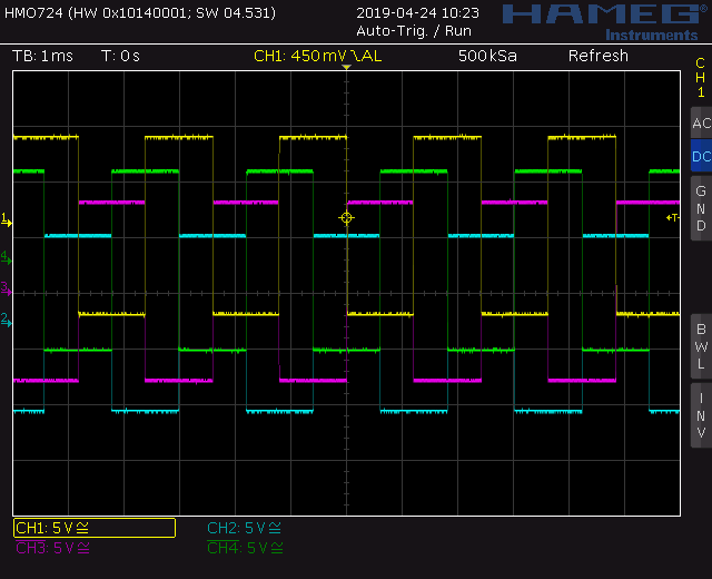
Trapezoid VCO screenshot: Square quadrature waveforms
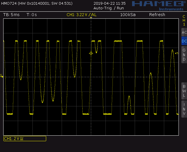
Trapezoid VCO screenshot: Through zero modulation
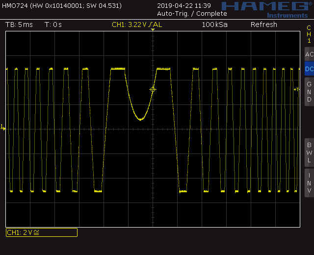
Trapezoid VCO screenshot: Through zero modulation
Top
Calibration
- V/Oct adjust
- Low frequency: Set the frequency to about 100Hz
- Apply +1V to the V/OCT input (Use Scaled Voltage Reference or keyboard). The frequency should double
- Adjust Trimmer TR_2 to until it works.
- High frequency: Set the frequency to about 2500Hz
- Apply +1V to the V/OCT input (Use precision voltage source or keyboard). The frequency should double
- Adjust Trimmer TR_1 to until it works.
- Repeat low and high frequency trim.
- A more elaborate procedure is found here: NGF: VCO Core two
- OTA offset voltage
- Remove DG409
- Ground the V/Oct input
- Disconnect P4 or set it to center. Ground the wiper connector.
- Set P1 (coarse frequency) slightly below 12:00.
- Set P2 (fine frequency) to center.
- Set P3 (FM log) to zero
- Set P5 (TZ mod) to zero
- Measure the DC offset at pin 13 of the OTA. Adjust trimmer TR1 to zero.
- Measure the DC offset at pin 12 of the OTA. Adjust trimmer TR2 to zero.
Building hints
- R7 (2k tempco 3300ppm) is mounted beneath the SSM2220
- Match C4 and C5
- Match C6 and C7
- Match R29, R31
- Match R10, R11
Special parts
- The SSM2220 could be replaced with two (hand matched) transistors
- The OTA CA3280 could be replaced with the AS3280 (not tested though).
Download
Trapezoid VCO documentation downloadTrapezoid VCO Gerber files download
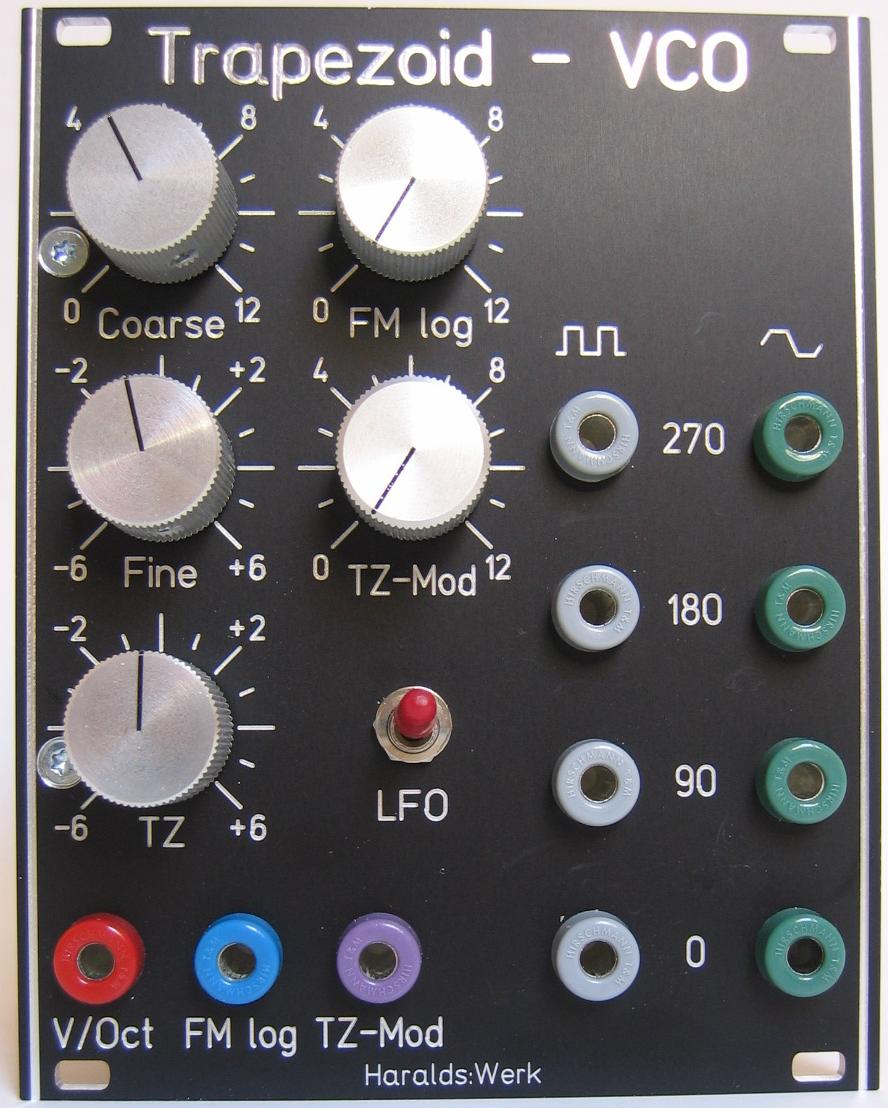
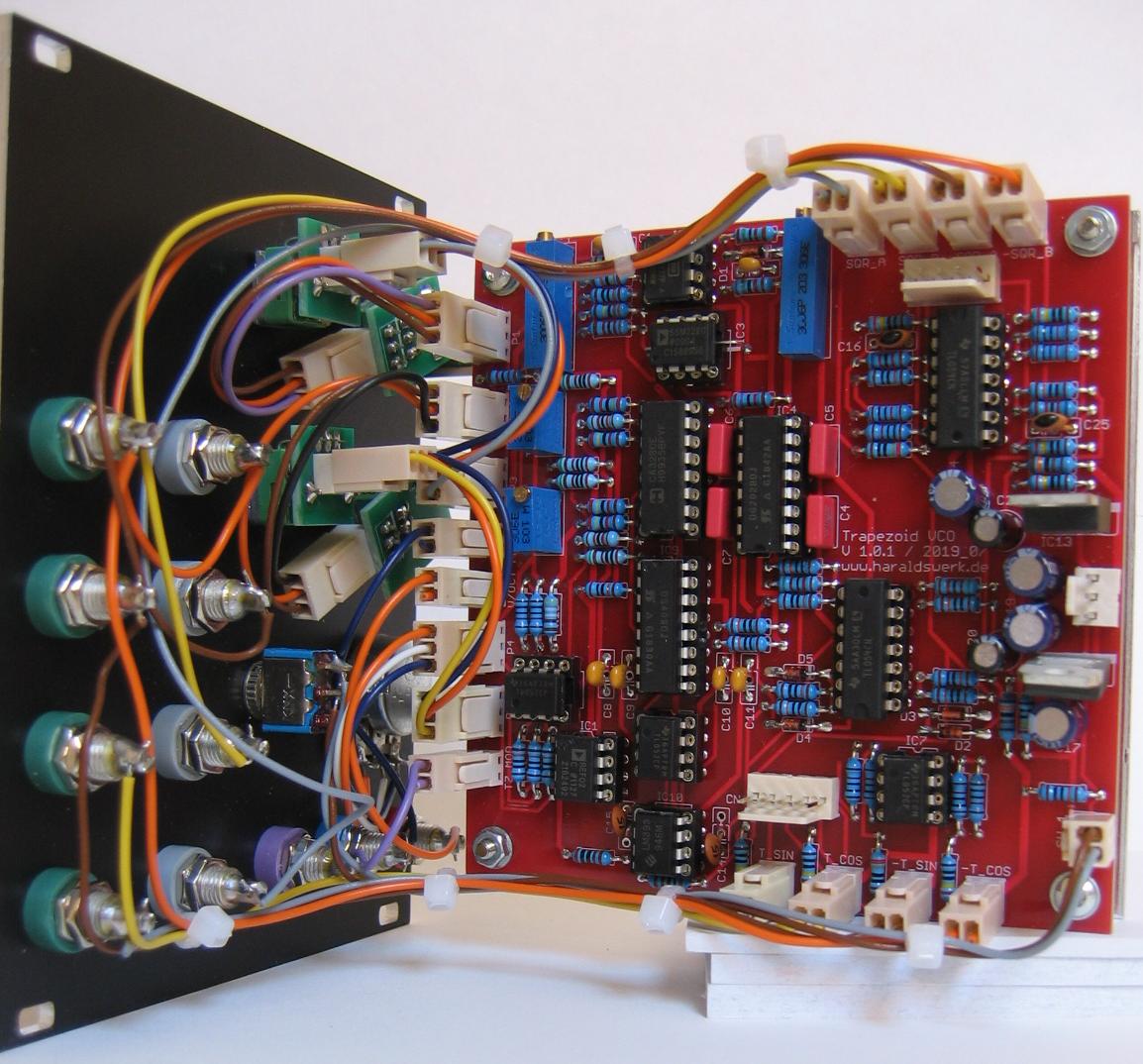
Trapezoid VCO: Front view
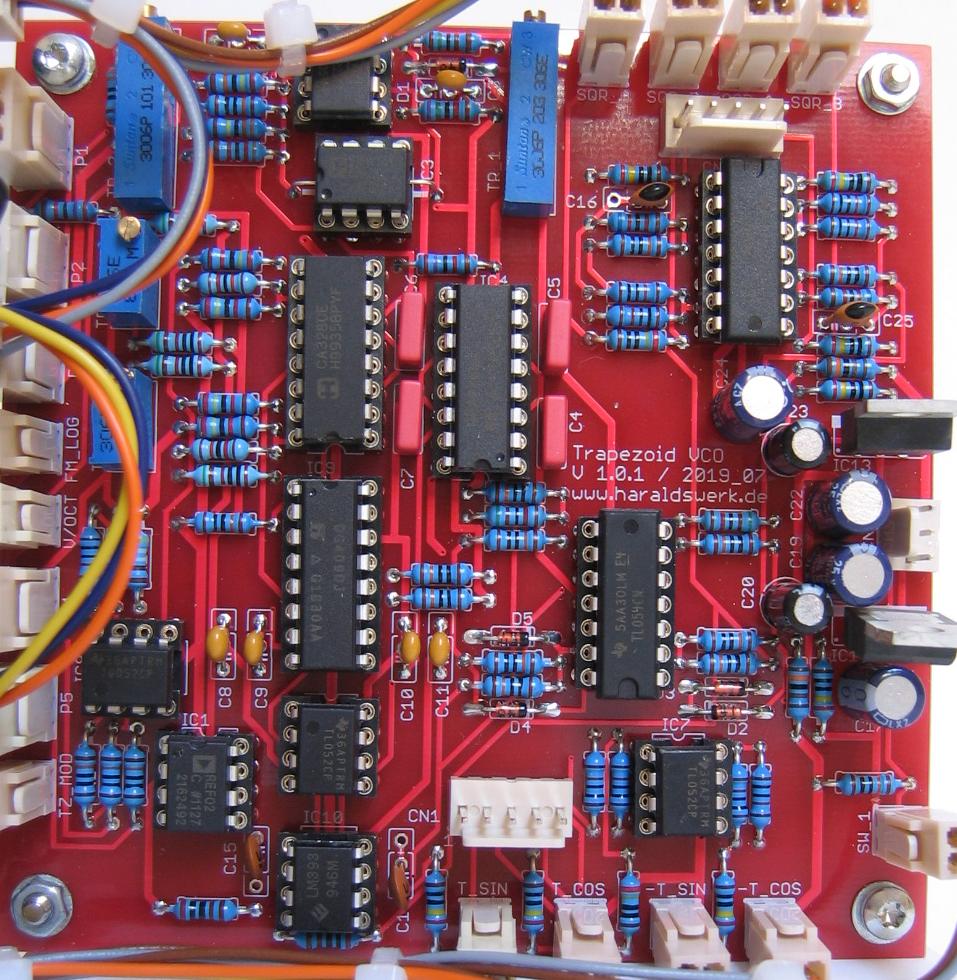
Trapezoid VCO: Populated PCB