Motivation

This PCB is part of my Bark Scanning Filter project. You can find more information on the Bark Scanning Filter project page
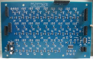
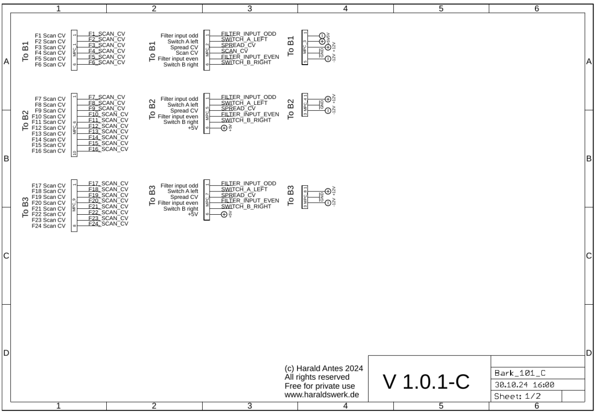
This PCB builds the heart of the Bark Scanning Filter. The scanner unit. The PCB connects all the necessary signals and control voltages between left, right and middle building block. And it holds all building blocks mechanical together. For understanding how everything works together please have a look at the block diagram on the project page.
Implementation
Schematic

Bark Scanning Filter: PCB C scanner unit schematic 01

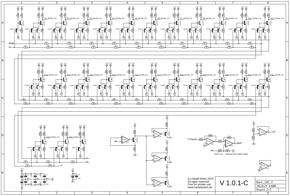
Bark Scanning Filter: PCB C scanner unit schematic 02
Description:
On the second page you can see the constant current sources and the scanner circuitry. There are basically 24(26) transistor switches which are controlled by comparing two voltages build woth two resistor ladders.
Calibration
- None
Building hints
- Leave R132 out and replace R133 with solder bridge or 0R.
Special parts
- None
Download
Bark Scanning Filter PCB C documentation downloadBark Scanning Filter PCB C Gerber files download