Motivation

This PCB is part of my Bark Scanning Filter project. You can find more information on the Bark Scanning Filter project page
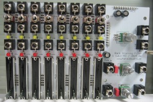
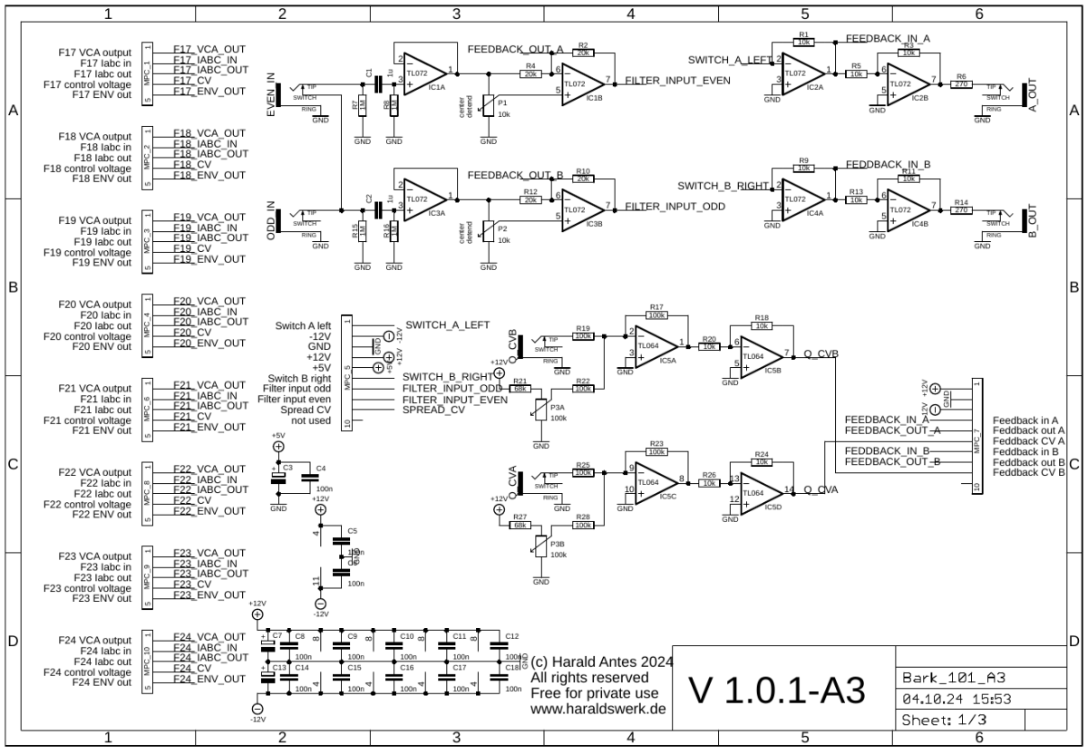
This PCB holds the audio inputs for the odd and even filters. The odd input is normaled to the even input. Both inputs have attenuverters. Those makes for interesting sonic effects when the feedback is engaged. The outputs A and B sums the individual outs from the filters according to the position of the select switches (A, B, off). The Q potentiometer adjust the amount of feedback used. The feedback is voltage controllable. The PCB holds the single outputs for the Bark filters 17-24, the envelope outs, the control voltage ins and the manual fader controls for the dedicated VCA's as well. The control voltages for the VCA's are signaled with LED, as well as envelope outputs for each channel. For understanding how everything works together please have a look at the block diagram on the project page.
Implementation
Schematic

Bark Scanning Filter: PCB A3 schematic 01

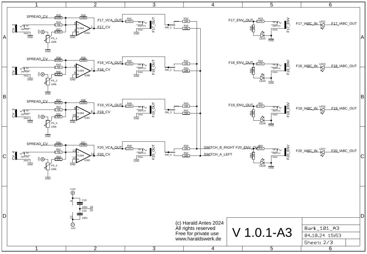
Bark Scanning Filter: PCB A3 schematic 02

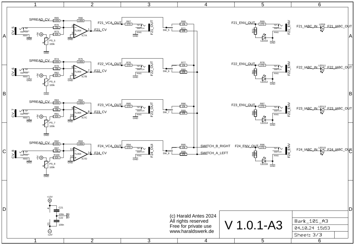
Bark Scanning Filter: PCB A3 schematic 03
Description:
On page one you can see the inputs and outputs as well as the manual control. On two and three you can see the summing nodes for control voltages and the selection switches for the A and B output channels. As well as input and output jacks and the signal LED.
Calibration
- None
Building hints
- Solder the connectors on the backside before placing the parts on front of the PCB.
Special parts
- None. The faders are from Befaco, the jacks from Thonk.
Download
Bark Scanning Filter PCB A3 documentation downloadBark Scanning Filter PCB A3 Gerber files download