Motivation

This is the Eurorack version of my NGF 12dB Multimode VCF.This filter type is widely used in many synthesizers. You can find it in Electronotes or in the SEM modules and in many other synthesizers as well. Nonetheless I have made some changes and adds. I wanted the filter to sound clean with no feedback and the feedback going from soft to very harsh. And usable for pinging (percussion). So I used the the CA3280 for good clean audio (You can use the newly available AS3280 instead). And added a voltage controlled feedback loop going from soft to harsh. This can give the filter a harsh sound and a lot of character. You can adjust the this behavior over a wide range with the calibration trimmers or changing one resistor and capacitor.
Specs and features
- 12dB voltage controlled multimode filter
- Two inputs for easy mixing
- Low pass, high pass, band pass and notch filter output
- Positive and negative ENV control with sign changer
- Temperature compensation with KTY81-110
- CV inputs for linear TM, log TM, envelope, V/Oct tracking and emphasis
- Runs on +/-12V and +/-15V (with minor resistor value changes for best performance)
- Power consumption around 80mA each rail
Implementation
Schematic

12dB Multimode VCF schematic: Control board

12dB Multimode VCF schematic: Main board
Description:
The point of interest in this schematic is the feedback loop. R1 and C1 on the main PCB determines the feedback amount. The feedback is always set to max. You can proof this with removing IC3 and IC4 from the main PCB. You will see/hear it. This lead to the conclusion that the feedback is not increased by the voltage controlled IC4(OTA2). The voltage control for the feedback loop dampens the feedback! All other parts of the schematic are widely used common circuitry.
Calibration
First make a gross function test. All in and outs should work as expected and all potentiometer have some effect.
The OTA DC offset calibration is a bit tricky. This is because of the DC coupling of the filter and the DC feedback loop.
- OTA DC offset
- Remove IC1 TL072BCN, IC3 TL071BCN and IC4 CA(AS)3280 from the main PCB.
- Set cut off potentiometer to max, feedback potentiometer to min. All other to min.
- To measure a voltage at the output of an OTA you have to apply a load. Easiest way here is to use the tip of your probe. Connect the tip of your probe with a 10k resistor to ground. Use a ground from the board (Ground pin of the ThonkiCon).
- Adjust IC2OTA1: Measure the voltage at LP_1. Set the voltage to zero with TR_2.
- Connect R4 to ground. at the side which is connected to pin1 of IC1. This provides a defined potential to the following OTA inputs.
- Adjust IC2OTA2: Measure the voltage at LP_2. Set the voltage to zero with TR_1.
- Insert IC4OTA.
- Adjust IC4OTA2: Measure the voltage at LP_3. Set the voltage to zero with TR_3.
- Put IC1 and IC3 back in.
- Initial frequency
- Apply a sine with 10Vpp and the lowest frequency you want to filter to the input (Most common 20..40Hz).
- Close the Cut off pot completely. No feedback.
- Adjust Trimmer TR_1 (control PCB) for zero audio output with a scope.
- I use the 12dB output here. Which means you'll still have some signal bleed through at the 6dB output. If you don't like this use the 6dB output here.
- Feedback damping
- Apply a 1kHz square signal to the input.
- Turn the feedback potentiometer to zero.
- Turn the cut off potentiometer to maximum.
- Adjust TR_4 (main PCB) so that there is no overshot on the rising edge of the square.
- V/Octave
- Apply a 1kHz square signal to the input.
- Turn the cut off potentiometer to zero (No signal at the low pass output).
- Turn the feedback potentiometer to zero.
- Turn the FM log potentiometer to maximum.
- Apply 5V DC to the FM input (Keyboard or other precision control voltage source). You should see the square at the output now.
- Adjust TR_2 (control PCB) so that the filter is completely open.
- When turning down the FM Log potentiometer slightly or lower the input voltage you should see the edges of the square rounding off.
- Check initial frequency setting again. It might be off due to the V/Octave calibration. Repeat initial frequency and V/Octave calibration until it is settled.
With the setting for initial frequency, feedback damping and V/Octave you can give the filter your own character over a wide range. First use the above calibration and the move on to your own taste if you want.
TopBuilding hints
- You can replace the CA3280 with the AS3280 which is now available.
- Match transistor Q1 with Q2
- For the adventurer: Play with the values R1 and C1 and the calibration settings.
Special parts
- None
Download
12dB multimode VCF control board documentation download12dB multimode VCF control board Gerber files download
12dB multimode VCF main board documentation download
12dB multimode VCF main board Gerber files download
12dB multimode VCF *.fpd file download
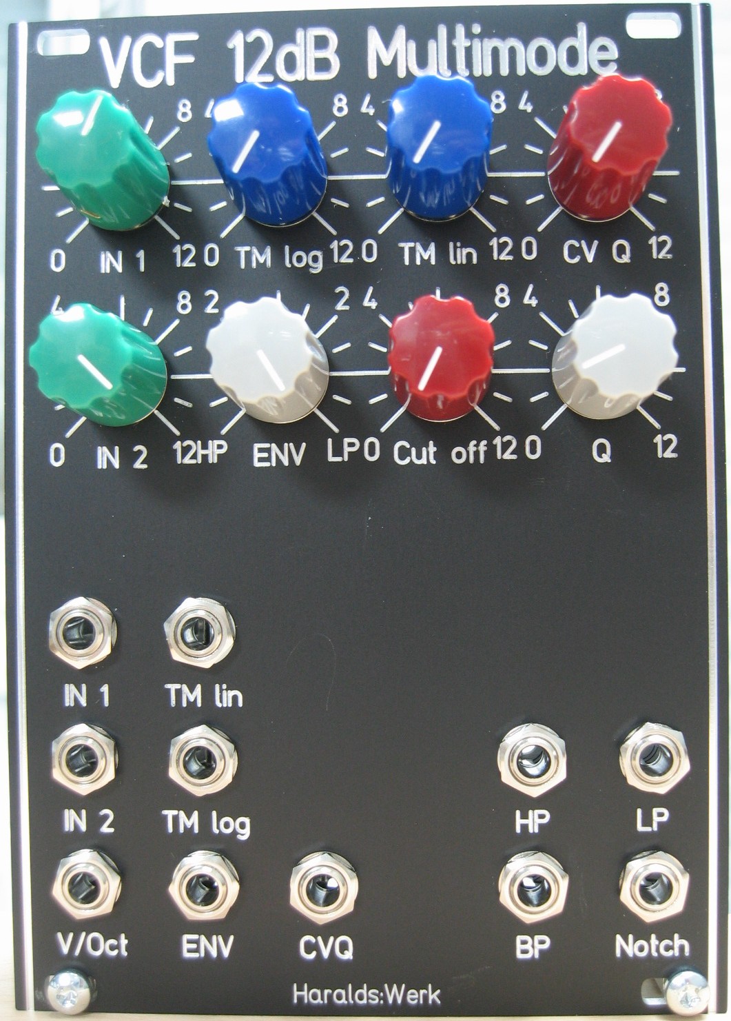
12dB multimode VCF: Front view
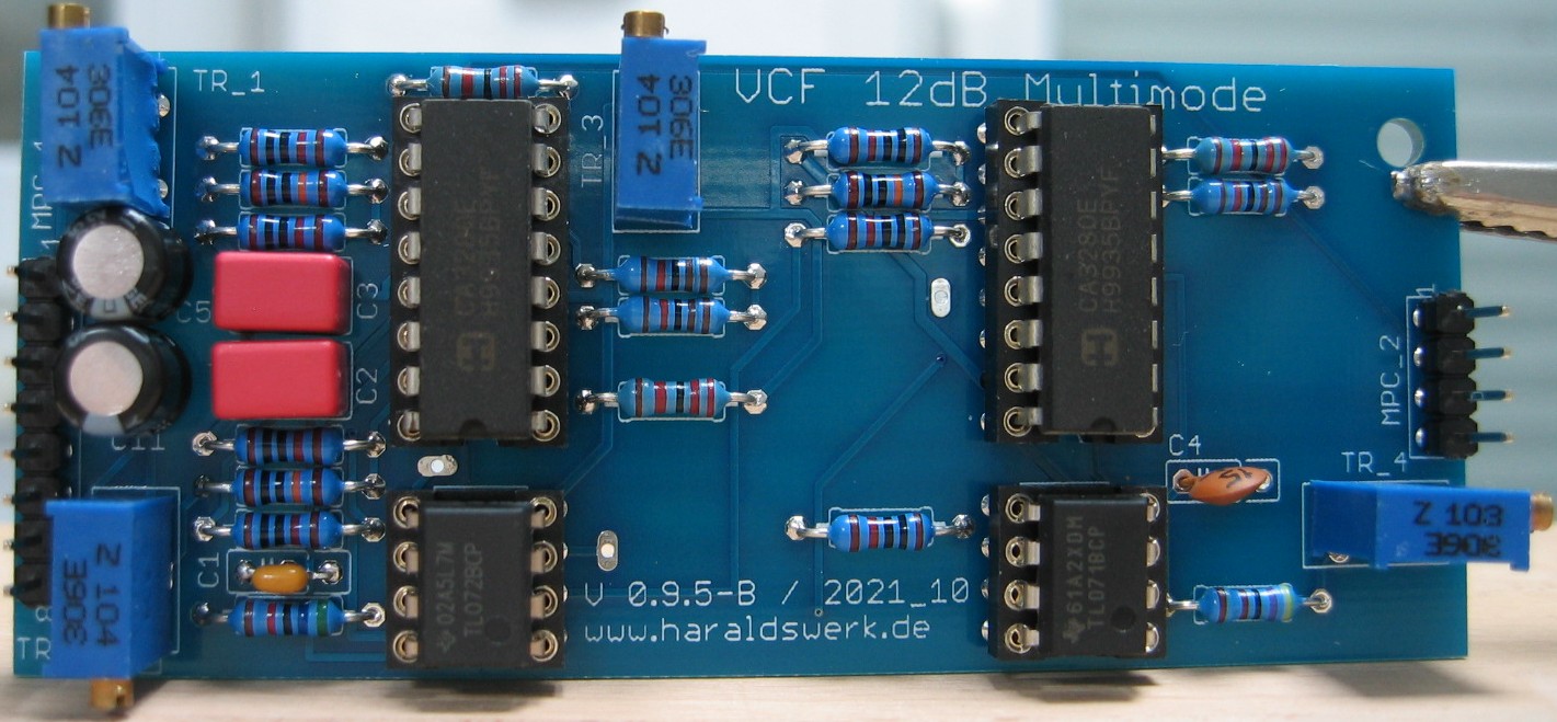
12dB multimode VCF: Populated control PCB
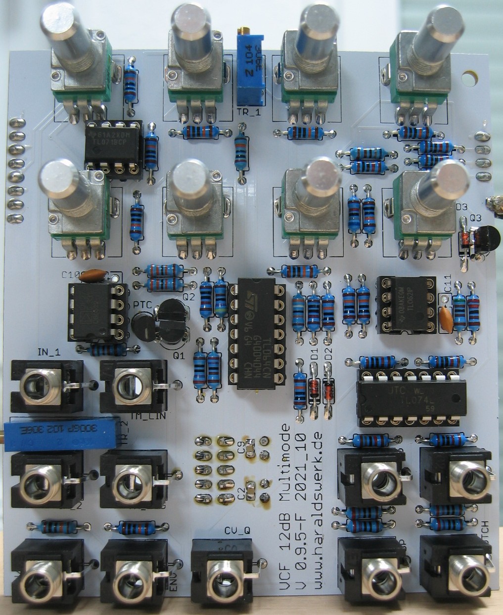
12dB multimode VCF: Populated main PCB
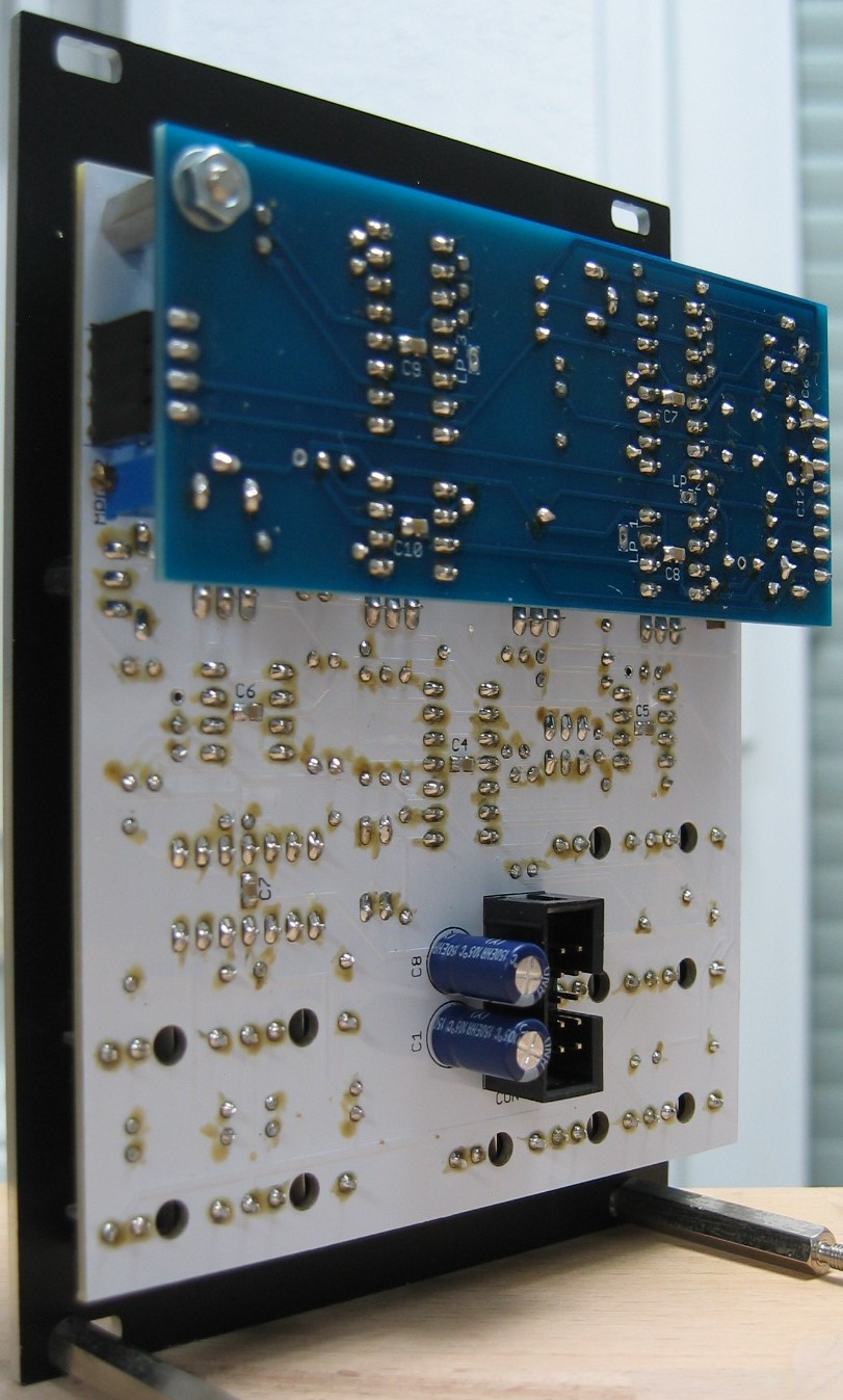
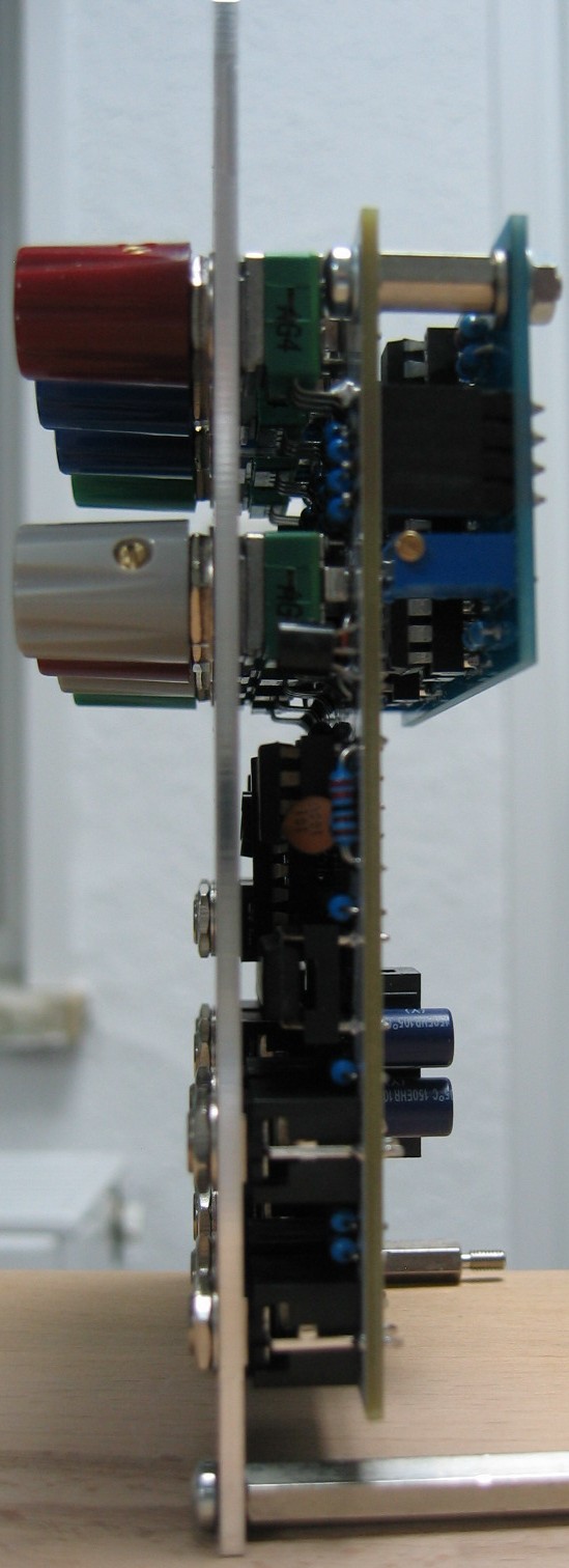
12dB multimode VCF: Back view
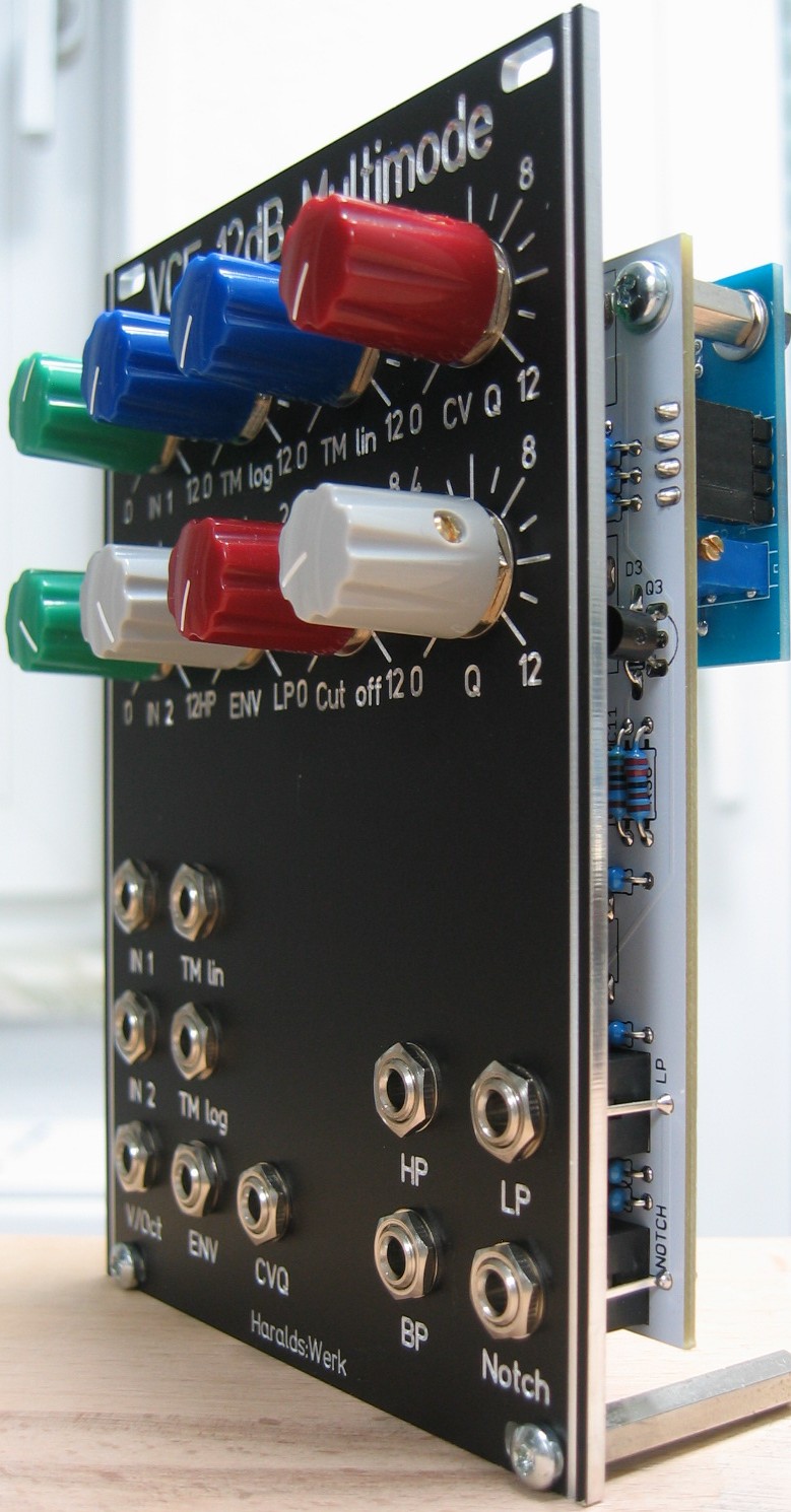
12dB multimode VCF: Half front view