Motivation
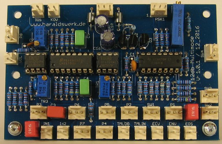
This is my take on the 12dB Multimode VCF. This filter type is widely used in many synthesizers. You can find it in Electronotes or in the SEM modules and in many others as well. Because this one is for my Nest Generation Formant project i started with the original Elektor Formant schematic and added my changes to the design. All parts are updated to today (2017/4) available parts. The connections are the same as in the original to keep the possibility for internal wiring. If you don't need those features just leave them out. This PCB provides all basic functions as in the original Elektor Formant. The additional functionality is put on an add-on board. The The CA3080 are replaced with LM13700. The JFET transistors are replaced with OpAmps. The signal level is raised to 10Vpp for a better signal to noise ratio. The exponentiator for generating Iabc for the OTA's is temperature compensated. The only additional function on this PCB is the linear TM input. All other additional functions are on the add-on board.
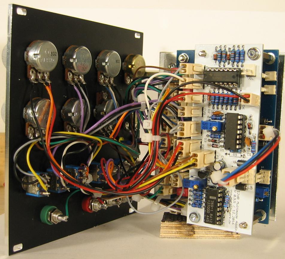
The add-on board provides voltage control for Q, a sign changer for the ENV input for easier use when the filter is switched to high pass mode and volume indicator.
Specs and features
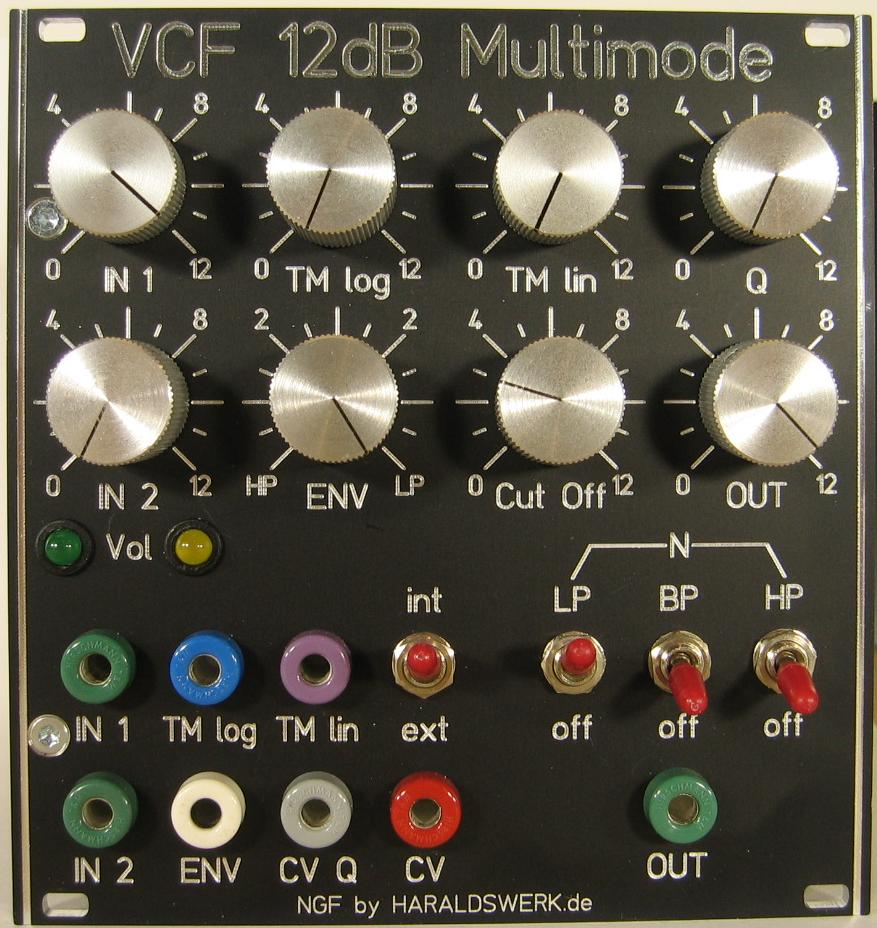
- 12dB highpass filter, 12dB lowpass filter, 6dB bandpass filter, notch filter
- Temperature compensated exponentiator
- 10Vpp signal level
- TM log input
- TM lin input
- Positive and negative ENV control (with AddOn PCB)
- Volume display (with AddOn PCB)
- Voltage controlled Q (with AddOn PCB)
- Runs on +/-15V and +/-12V (with minor resistor value changes)
- Schematic 12dB Multimode VCF
- Pictures
- Download docs
Implementation
Schematic
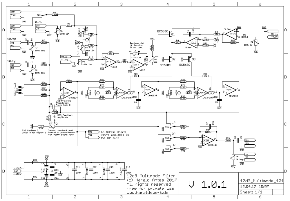
NGF 12dB Multimode VCF
Description:
There are a lot descriptions of those state variable filters out there. I feel no need to add another one.
TopCalibration
DC offset OTA
- Remove IC2 and IC3
- (OTA1) Attach a 10k resistor from pin3 IC2 to ground.
- (OTA1) Turn Cut Off potentiometer full on.
- (OTA1) Measure the voltage at pin3 IC2. Adjust to zero with TR3
- (OTA2) Attach a 10k resistor from pin5 IC2 to ground.
- (OTA2) Turn Cut Off potentiometer full on.
- (OTA2) Measure the voltage at pin5 IC2. Adjust to zero with TR4
- Remove resistor and put the IC's back in
Offset
- Apply a square signal of about 500Hz to the input. Set the filter to lowpass mode.
- Set potentiometer P4 (Cut off) to max (15V). Set trimmer TR1 to ground.
- Turn TR1 slowly to -15V. You will see and hear that the edges of the square signal starts rounding.
- Adjust TR1 so that there is no audible damping of the overtones. This adjustment is not critical. No need for excessive precision.
V/Octave
- Set the filter to bandpass mode. Set Q fairly high. Connect CV from the keyboard. Set the VCO to about 500Hz when the highest key on the keyboard is pressed.
- Adjust P4 (Cut off) for maximum output at bandpass output.
- Press keyboard two octaves lower. Adjust TR2 for maximum output.
- Press keyboard two octave higher. Adjust P4 (Cut off) for maximum output at bandpass output.
- Press keyboard two octaves lower. Adjust TR2 for maximum output.
- Repeat until the output amplitude stays the same when the keys are pressed two octaves apart.
Special parts
None