Motivation
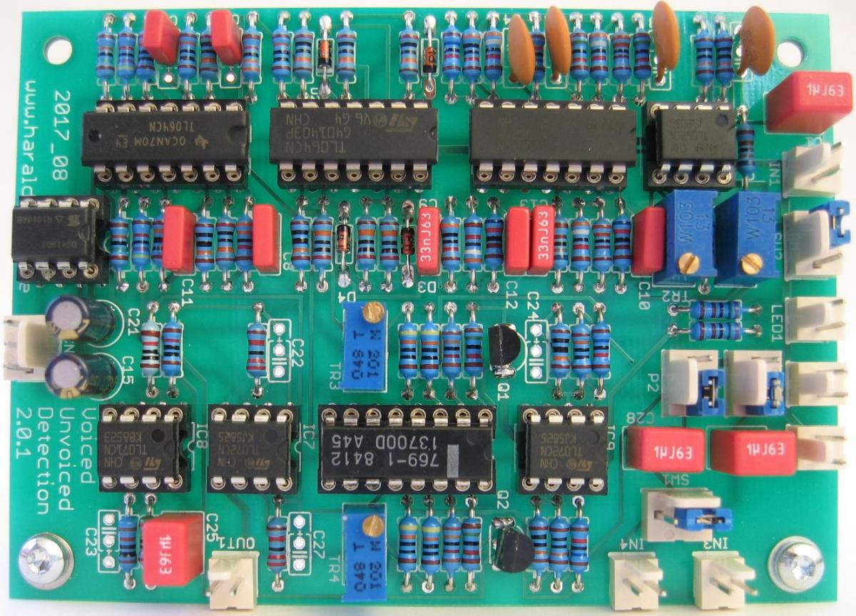
Here is the voiced - unvoiced detection module for my Vocoder project. It is made off a high pass and a low pass filter. The outputs of the filters are compared. The comparator switches the output signal between carrier and noise.
Specs and features:
- Voiced - unvoiced detection
- +/- 15V PSU. Runs on +/- 12V with minor resistor changes
- Schematic Vocoder voiced - unvoiced detection
- Documentation download
- Pictures
Implementation
Schematics
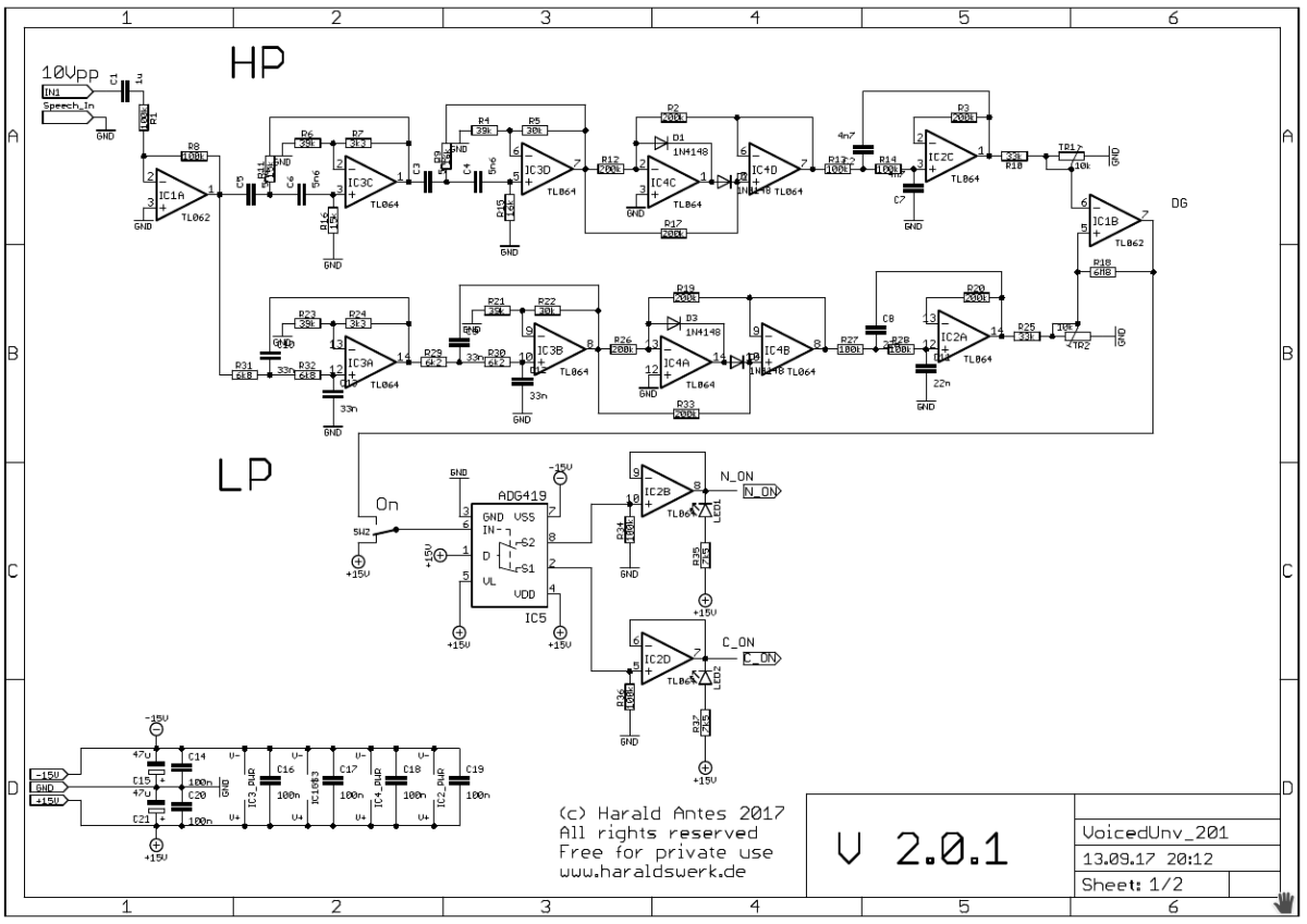
Vocoder voiced - unvoiced detection schematic 01
Description
The speech input signal derived from the speech input module initially reaches the buffer IC1A and is then split into two signals, each passing a filter. The high pass filter is constructed around IC3C and IC3D and the low pass around IC3A and IC3B. Their peak values are at 2500Hz and 600Hz respectively. The high pass filter is a Sallen Key filter, highly damped, gain around 5.6 dB. The low pass filter is constructed accordingly. Both filter sections have a slope of 24dB per octave to obtain a good separation. They are each followed by a precision full wave rectifier (IC4C, IC4D and IC4A, IC4B) and by a 12dB per octave smoothing filter. The rectified and calibrated filter output signals are now feed to a comparator IC1B. The voiced - unvoiced decision is taken by the comparator according to the signal levels. The comparator output steers the switch IC5 which selects if the carrier or the noise signal is send to the output.
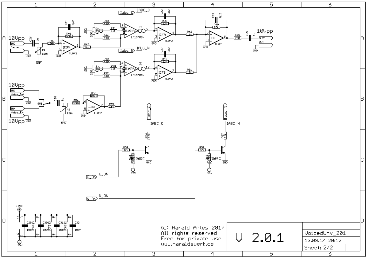
Vocoder voiced - unvoiced detection schematic 02
Description
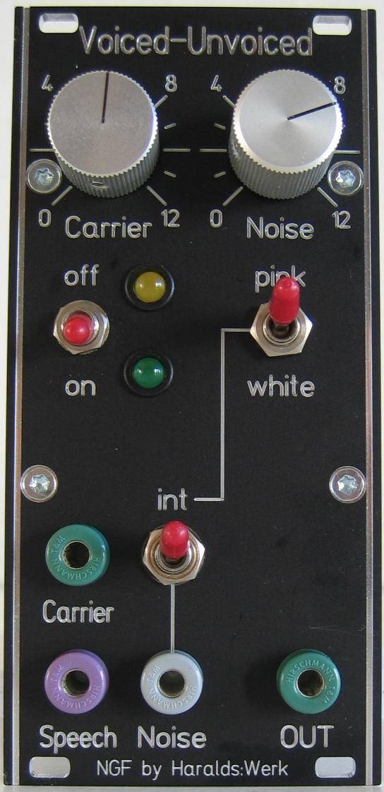
The carrier and the noise input are both fed to OTA's. The carrier input is buffered with IC9A, the noise input with IC9B. The noise input is switchable between internal and external source. The OTA's are turned on or off according to the signal from switch IC5 (schematic page 01).
Calibration
OTA's
- Remove IC7.
- Connect a 10k Resistor from pin 6 socket IC7 to ground.
- Apply a signal with 100Hz/10Vpp to input IN1 (speech input)
- Measure the voltage at pin 6 on the socket of IC7.
- Adjust to zero with trimmer potentiometer TR4
- connect a 10k Resistor from pin 2 socket IC7 to ground.
- Apply a signal with 3000Hz/10Vpp to input IN1 (speech input)
- Measure the voltage at pin 2 on the socket of IC7.
- Adjust to zero with trimmer potentiometer TR3
- Put IC7 back in
Voiced - unvoiced detection:
- The calibration depends a bit on your sonic preferences and may differ from application to application. But you can easily adjust it to your needs. Only two trimmer potentiometers are used. They determine the switching point of the comparator (the transfer frequency) between the voiced - unvoiced signal. Adjust TR1 and TR2 to your needs.
- For a starting point apply a square wave with 10Vpp 600Hz to IN1 (speech input). Adjust TR1 and TR2 so that the switching point is at 600Hz for a square wave. Move on from here according to your application needs. Best with alternately uttering "A" and "S" sounds in the microphone. Depending on results adjust TR1 and TR2.
Special parts
None.