Motivation
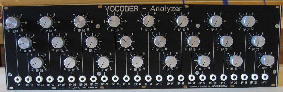
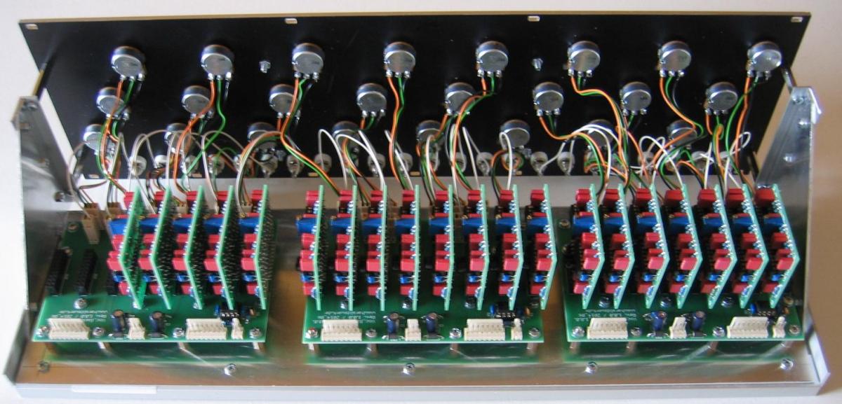
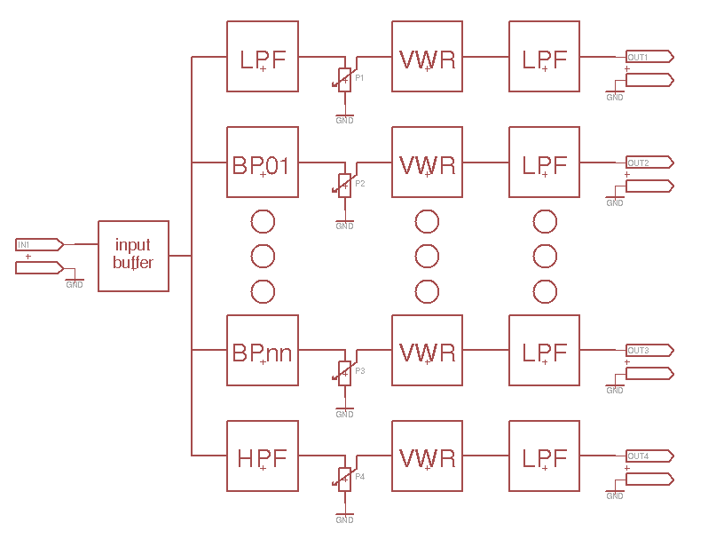
The analyzer part of a vocoder has the function to divide the incoming signal into frequency bands and to generate an analog output signal per band in dependency to the signal level. Because i wanted to be flexible what filter architecture and frequency distribution to use, i made the filters pluggable. So you can easily change filters and test different configurations. For the first attempt i used the filter architecture suggested by Jürgen Haible who derived them from the EMS 5000 vocoder. Other filters will follow. I added four more filters and moved the frequency of the high- and low pass. One backplane holds up to eight filters. So you can start small and add filters as you need
Specs and features:
- up to 24 filters
- input 1.25 Vpp (adjustable)
- output 0..5V DC / Channel
- variable number of filters
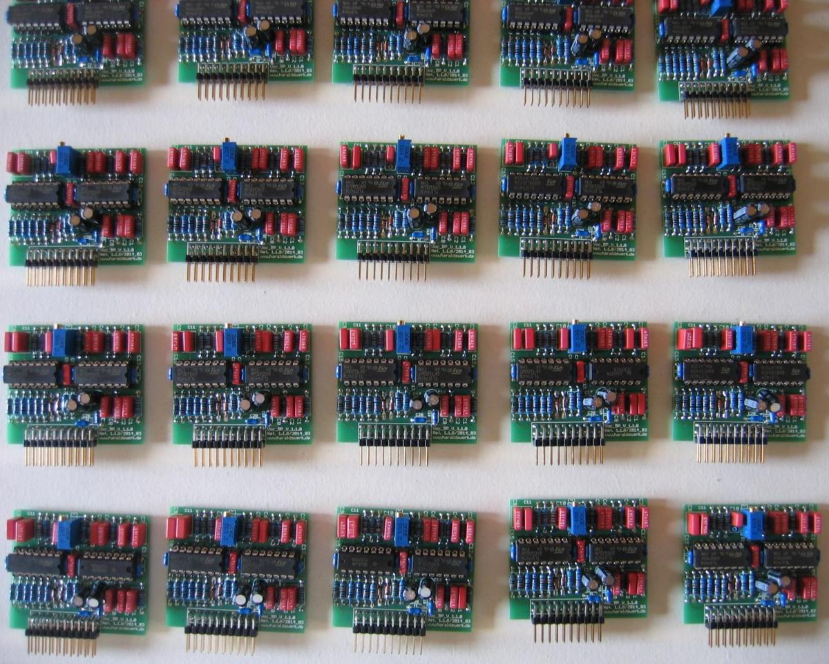
- exchangeable plug in filters
- +/- 15V PSU. Runs on +/- 12V as well (With minor changes in some component values)
- Schematic backplane
- Schematic high-pass filter
- Schematic bandpass filter
- Schematic low-pass filter
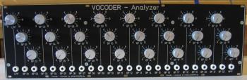
- pictures
Simulation
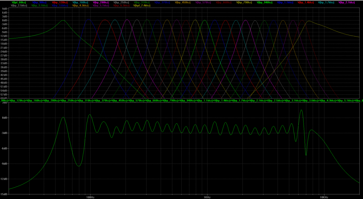
Vocoder Analyzer: level of individual filters and summarized output(from simulation)
Implementation
Vocoder Analyzer: Schematics
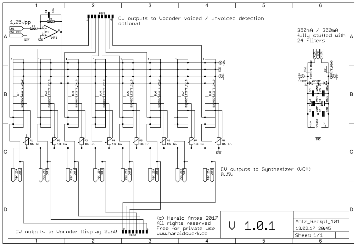
Vocoder Analyzer: Schematic backplane
Top
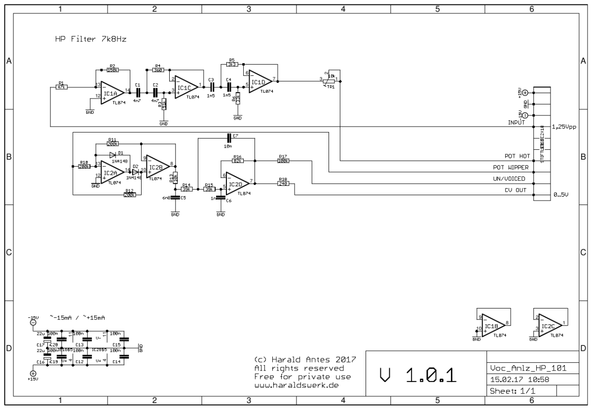
Vocoder Analyzer: Schematic high-pass
Top
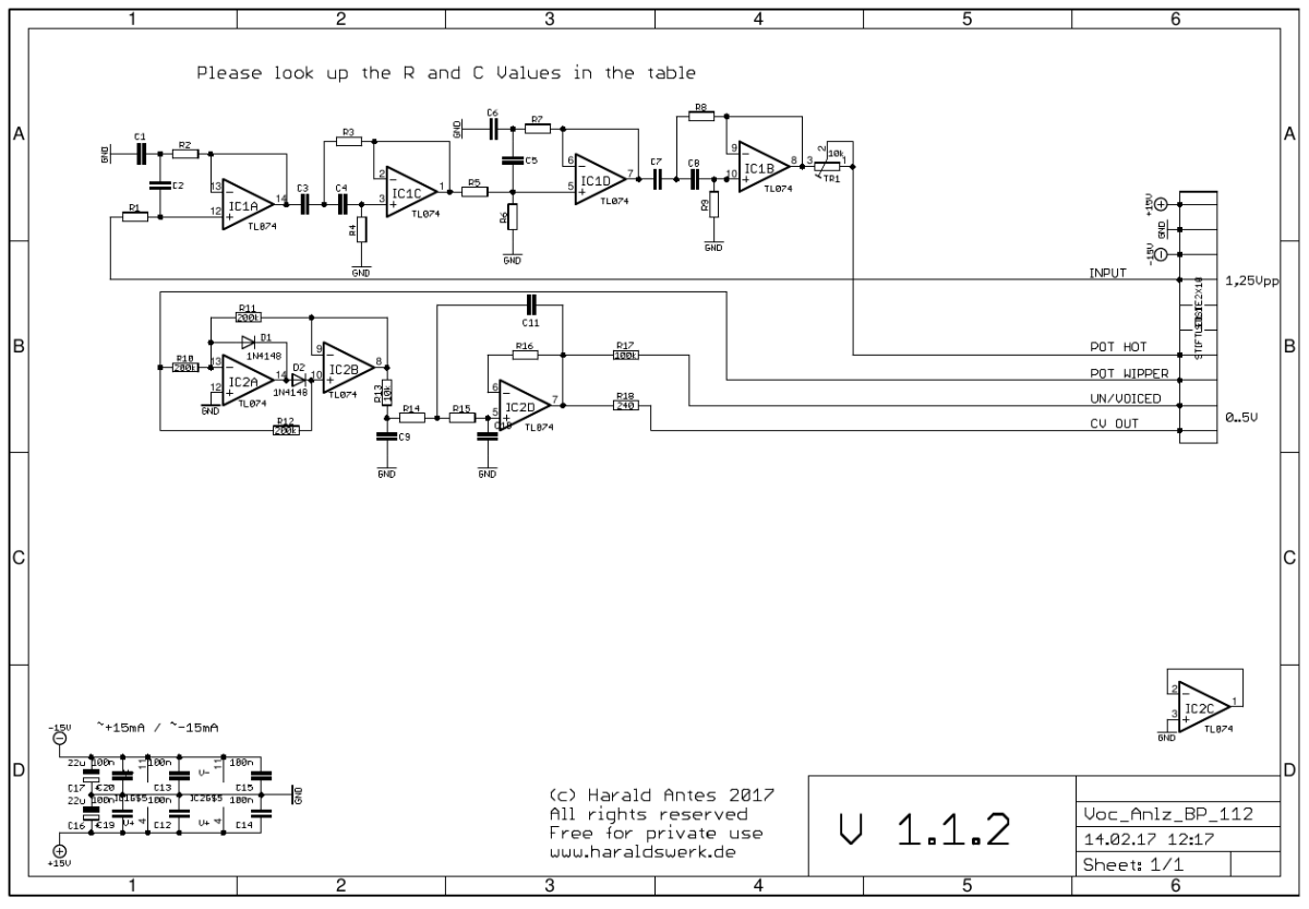
Vocoder Analyzer: Schematic bandpass
Top
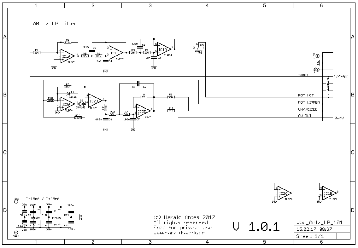
Vocoder Analyzer: Schematic low-pass
Top
Description
Backplane
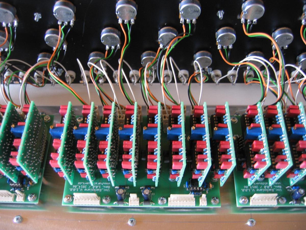
The backplane just holds everything together. The input is buffered with IC1. Input voltage for the filters should be 1,25Vpp. If you need to adjust the input voltage change the gain of IC1. There is an optional CV output (pin header) which can be used for voiced / unvoiced detection. Just sum up the appropriate filter CV outputs and make the decision. The other output (pin header) goes to the Vocoder Display unit. The socket boards holds the filters. The output voltage of each filter can be adjusted with a potentiometer.
High-pass
The high-pass filter is a Sallen-Key filter wtih 24 dB roll off followed by a precision full wave rectifier and a smothing filter for the DC. The output votage is adjusted with TR1.
Bandpass
The bandpass filters follows the description from Jürgen Haible. His design was inspired by the EMS 5000 Vocoder. I have added two more band pass filters on the high and low end. The roll off is 24 dB. Each band pass filter is followed by a precision full wave rectifier and a smoothing filter for the DC. The output votage is adjusted with TR1. The component values are given in the table.
Low-pass
The low-pass filter is a Sallen-Key filter with 24 dB roll off followed by a precision full wave rectifier and a smoothing filter for the DC. The output voltage is adjusted with TR1.
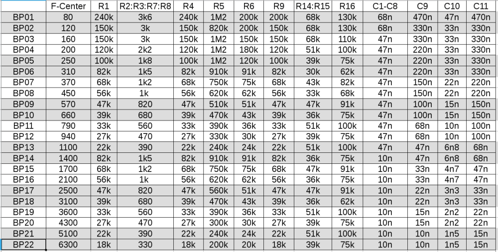
Vocoder Analyzer: Bandpass component values
Top
Calibration
- Let the filters warm up.
- Turn the output pot of the filter under test to max.
- Apply a sine signal from a frequency generator to the input with 1.25Vpp.
- Measure the DC output voltage of the filter under test
- Find the middle frequency of the filter under test by adjusting the generator frequency slightly. The frequency may differ a bit from the theoretical value due to component tolerances.
- Adjust the trimmer potentiometer in the filter under test until you have 5V at the output.
Special parts
You have to use 1% capacitors in the bandpass filters. Cheapest way to get them is selecting by hand. Buy a couple and measure. There is no need for absolute match. Relative match within the filter is sufficient. Keep in mind that you have to match the capacitor in the analyzer and the synthesizer part of the Vocoder per channel as well.