Motivation
This is my take on an harmonic oscillator with saw output. The oscillator multiplies the basic saw from one to ten. Every harmonic has an individual output and voltage controlled volume. The odd and the even outputs have separate summed outputs. The summed output is voltage controlled as well. You can scan through the outputs manually or voltage controlled. The depth and the channel spread is controlled by hand and voltage. This one is for the more adventures and experimental musician.
Specs and features
- Ten individual harmonic outputs with voltage control
- Odd harmonic output
- Even harmonic output
- Summed output
- Adjustable channel spread (width)
- Scanning the harmonics by hand
- Scanning the harmonics voltage controlled
- Octave switch
- Fine frequency setting
- FM log
- Power consumption up to 380mA each rail
Implementation
Schematic

Harmonic Oscillator schematic: Control board 01

Harmonic Oscillator schematic: Control board 02

Harmonic Oscillator schematic: Main board 01/01

Harmonic Oscillator schematic: Main board 01/02

Harmonic Oscillator schematic: Main board 02/01

Harmonic Oscillator schematic: Main board 02/02

Harmonic Oscillator schematic: Main board 03

Harmonic Oscillator schematic: Main board 04

Harmonic Oscillator VCO schematic: Control board

Harmonic Oscillator VCO schematic: Main board 01/01

Harmonic Oscillator VCO schematic: Main board 01/02

Harmonic Oscillator VCO schematic: Main board 02
Description:
This harmonic oscillator is a combination from different schematics which I already had used in other modules. The VCO is from my NGF project. The scanning circuitry is from my Scan and Pan module. Just enhanced it from 6 to 12 stages. Still based on the work of J. Donald Tillman and Jürgen Haible. The harmonics circuitry is inspired by Electronotes AN-190.
Harmonic Oscillator screenshot: 1, 2, 3, 4 harmonics
Harmonic Oscillator screenshot: 1, 5, 6, 7 harmonic
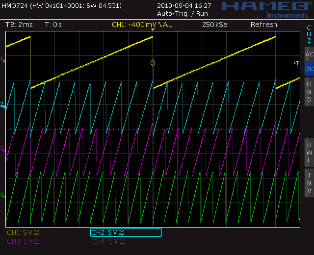
Harmonic Oscillator screenshot: 1, 8, 9, 10 harmonic
Top
Calibration
- First make a gross test. You should have a signal at every output, pots and inputs reacting.
- VCO calibration: Temperature CA3036
- Remove the control board from the VCO.
- Connect the VCO to the PSU.
- Adjust TR_1 on 1.1.0-B for the wanted temperature. The temperature should be above the ambient temperature in your case.
- I adjust mine to 45deg Celsius. Using a infrared thermometer.
- Put the control board back on.
- VCO calibration: DC offset, gain
- Connect a scope to the VCO output. Watch the saw.
- Adjust TR1 on 1.2.0-C for zero DC offset.
- Adjust TR3 on 1.2.0-C for a gain of +/-5Vpp
- This is crucial for the later calibration of the saw multipliers.
- VCO calibration: V/Octave
- The calibration procedure for the VCO is the same as described here: NGF VCO Core two
- TR1 on 1.1.0-B is the V/Octave low end trim. TR2 on 1.2.0-C is the V/Octave HF trim.
- OTA offset voltage
- Remove board D and E (The wave multipliers)
- Set the slider pot for channel one (2..10) to max
- Measure the output voltage at the individual output of channel one (2..10)
- Adjust trimmer TR_1 (TR_4, TR_7, TR_9, TR_2, TR_5, TR_8, TR_10, TR_3, TR_6) for zero volts at the output
- Move on to next channel
- Set all channel sliders to zero
- Set the sum channel slider to max
- Measure the output voltage at the sum output for zero volts at the output
- Adjust trimmer TR_11
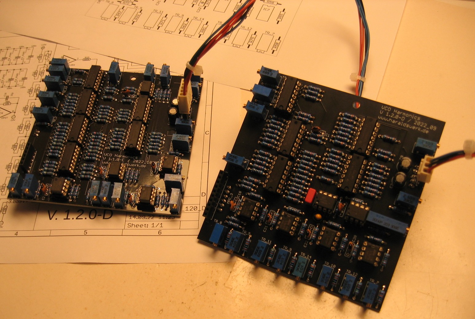
You have a lot to calibrate. Be patient and careful. You have to repeat the wave multiplier calibration for every multiplier. I only describe the calibration of one multiplier though. All the others have the same procedure. You only need to replace the figures and names used. First step is setting the DC working point for the wave multipliers. This should be done for all ten in one go. Therefore I made some extra cables to connect the boards together and to the PSU as pictured above.
Harmonic Oscillator: Calibration board D and E
- Wave multiplier: DC working point
- Read the right voltage from the schematic. 3.57V for the seventh.
- Adjust TR_6 for 3.57V at pin10 of IC3.
- Adjust TR_18 for -3.57V at pin12 of IC10.
- Repeat until it fits. The trimmers are not independent because they are both part of the voltage divider chain.
- Set the DC working points for the other wave multipliers with the same procedure.
- Connect the boards and the VCO
- The output (for the seventh) should look something like this:
Harmonic Oscillator: Calibrating DC working point
- Wave multiplier: Multiplication
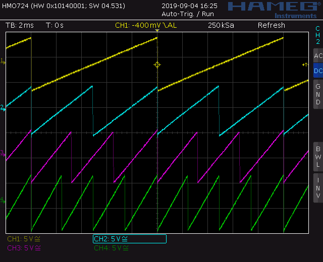
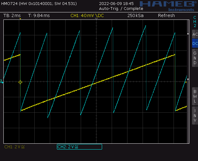
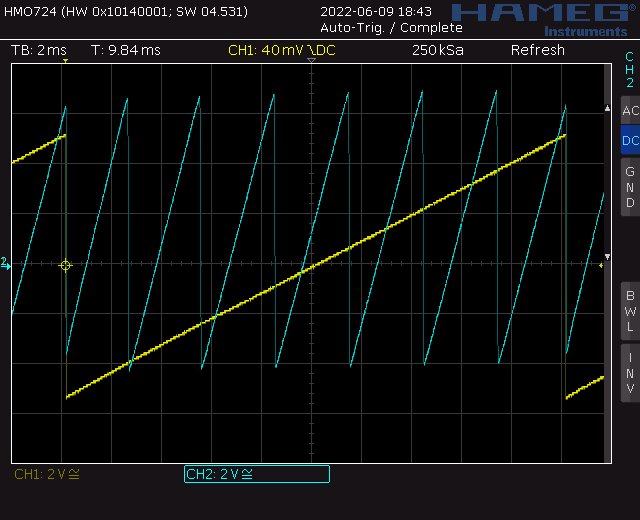
- It is crucial to use the dedicated and properly calibrated VCO for the calibration. The calibration depends on the voltage of the output signal from the used VCO (10Vpp). Here I describe the calibration of the seventh harmonic. Change the voltage and the used trimmers according to the schematic. Use a two channel oscilloscope set to DC. Connect channel one to the output of the first channel and set the trigger this channel. Connect channel two to the harmonic you are calibrating. Don't forget to set the slider for the actual channel to max.
- As you can see on the screenshot above the count of the harmonics is wrong. It counts only to five, should be seven in our example.
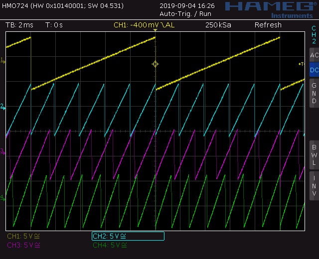
- The multiplication depends on the input signal. Adjust TR_4 until your count goes to seven.
- The output should look like this:
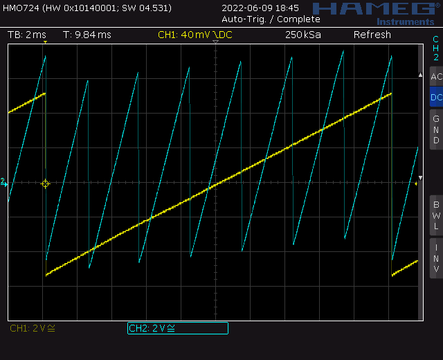
Harmonic Oscillator: Calibrating harmonics count
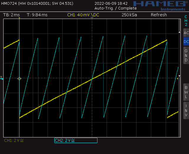
- Wave multiplier: Alignment
- Adjust TR_15 until the peaks of the signal are on the same level
- The output should look like this now:
Harmonic Oscillator: Calibrating alignment
- Wave multiplier: DC offset
- Adjust the remaining DC offset with TR_9
- The final result should look like this:
Harmonic Oscillator: Calibrating DC offset
You have to repeat this procedure for every harmonic. Replace the voltage and the trimmers in the example for the seventh with the values and names given in the schematic. Be patient. Repeat the procedure until you are satisfied.
Top
Building hints
- None
Special parts
- I use Befaco sliders here.
Download
Harmonic Oscillator control board documentation downloadHarmonic Oscillator control board Gerber files download
Harmonic Oscillator main board 01 documentation download
Harmonic Oscillator main board 01 Gerber files download
Harmonic Oscillator main board 02 documentation download
Harmonic Oscillator main board 02 Gerber files download
Harmonic Oscillator main board 03 documentation download
Harmonic Oscillator main board 03 Gerber files download
Harmonic Oscillator main board 04 documentation download
Harmonic Oscillator main board 04 Gerber files download
Harmonic Oscillator VCO control board documentation download
Harmonic Oscillator VCOcontrol board Gerber files download
Harmonic Oscillator VCO main board 01 documentation download
Harmonic Oscillator VCO main board 01 Gerber files download
Harmonic Oscillator VCO main board 02 documentation download
Harmonic Oscillator VCO main board 02 Gerber files download
Harmonic Oscillator *.fpd file
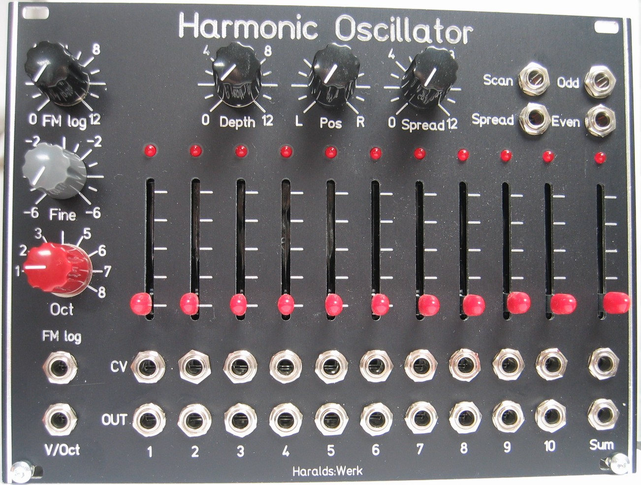
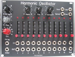
Harmonic Oscillator: Front view
Harmonic Oscillator: Front view
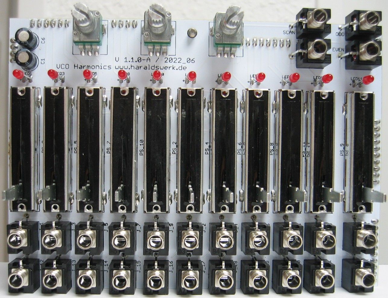
Harmonic Oscillator: Populated control PCB top
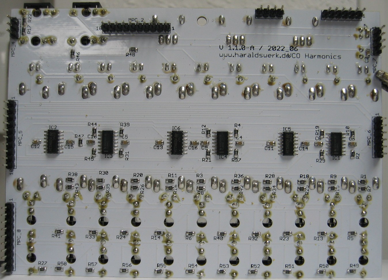
Harmonic Oscillator: Populated control PCB back
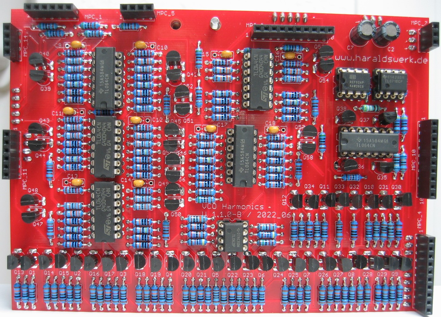
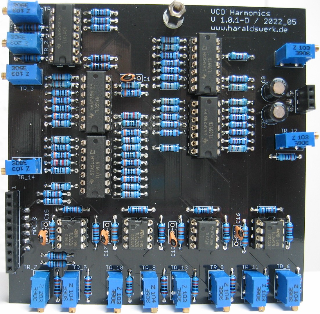
Harmonic Oscillator: Populated main PCB 01
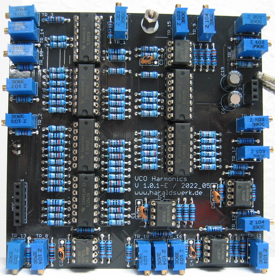
Harmonic Oscillator: Populated main PCB 02
Harmonic Oscillator: Populated main PCB 03
Harmonic Oscillator: Populated main PCB 04
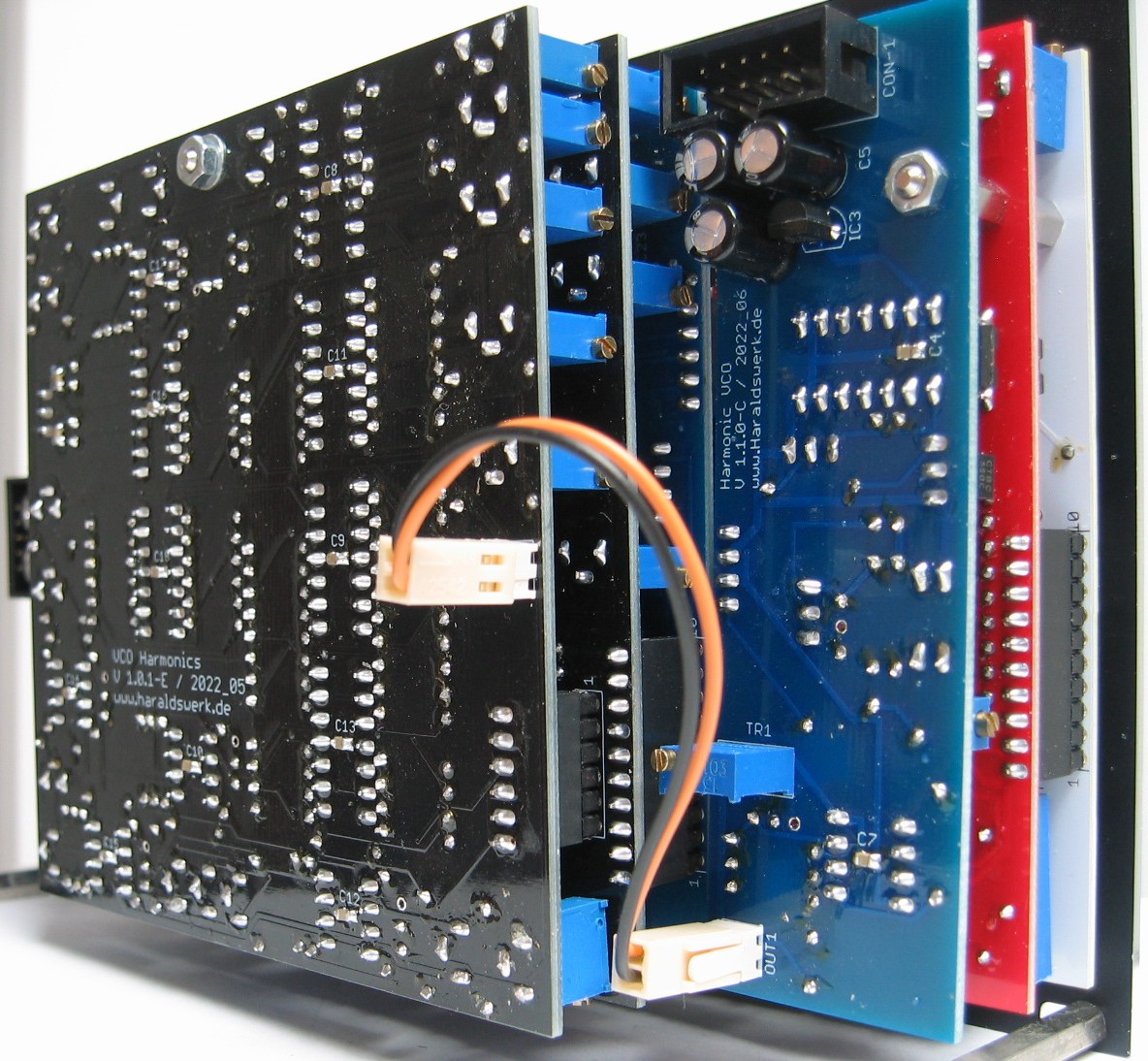
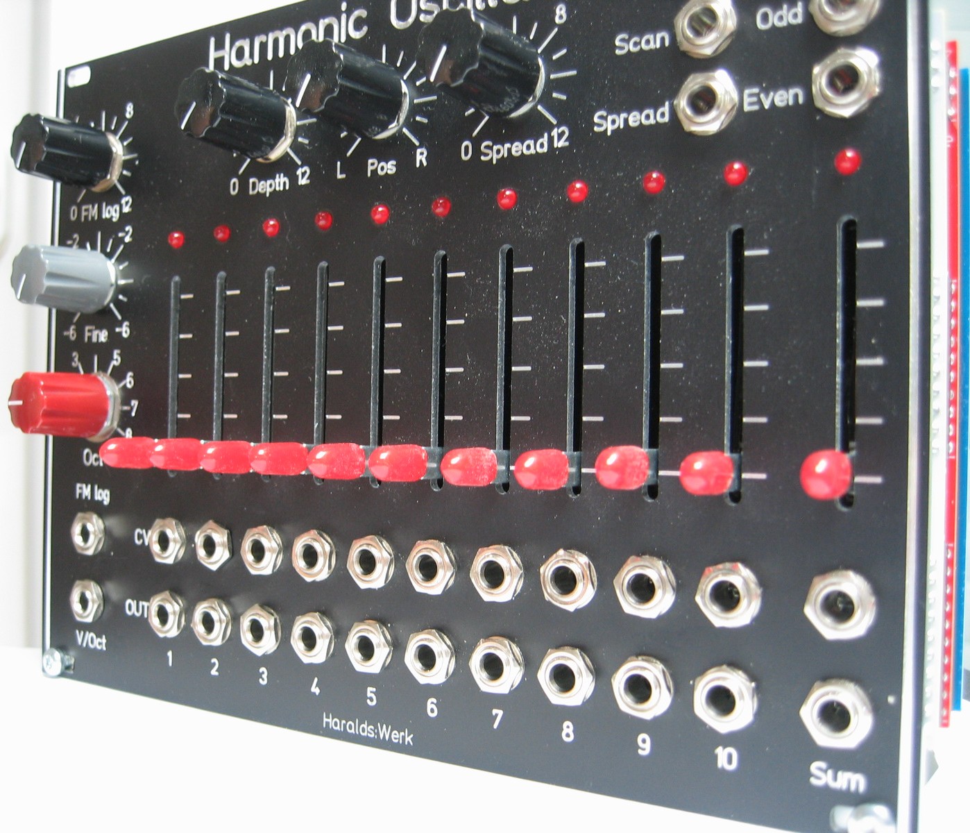
Harmonic Oscillator: Back left view
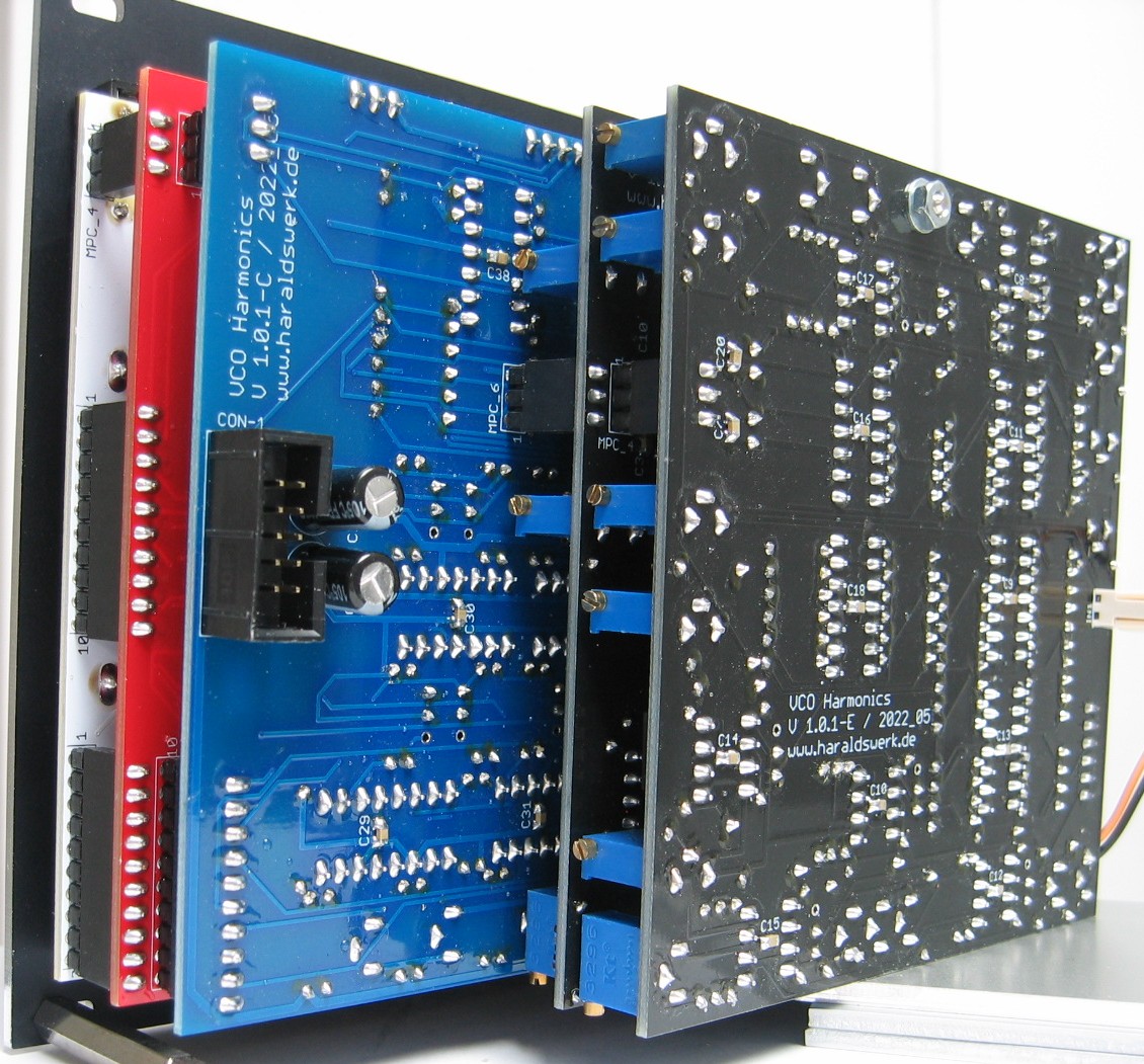
Harmonic Oscillator: Back right view
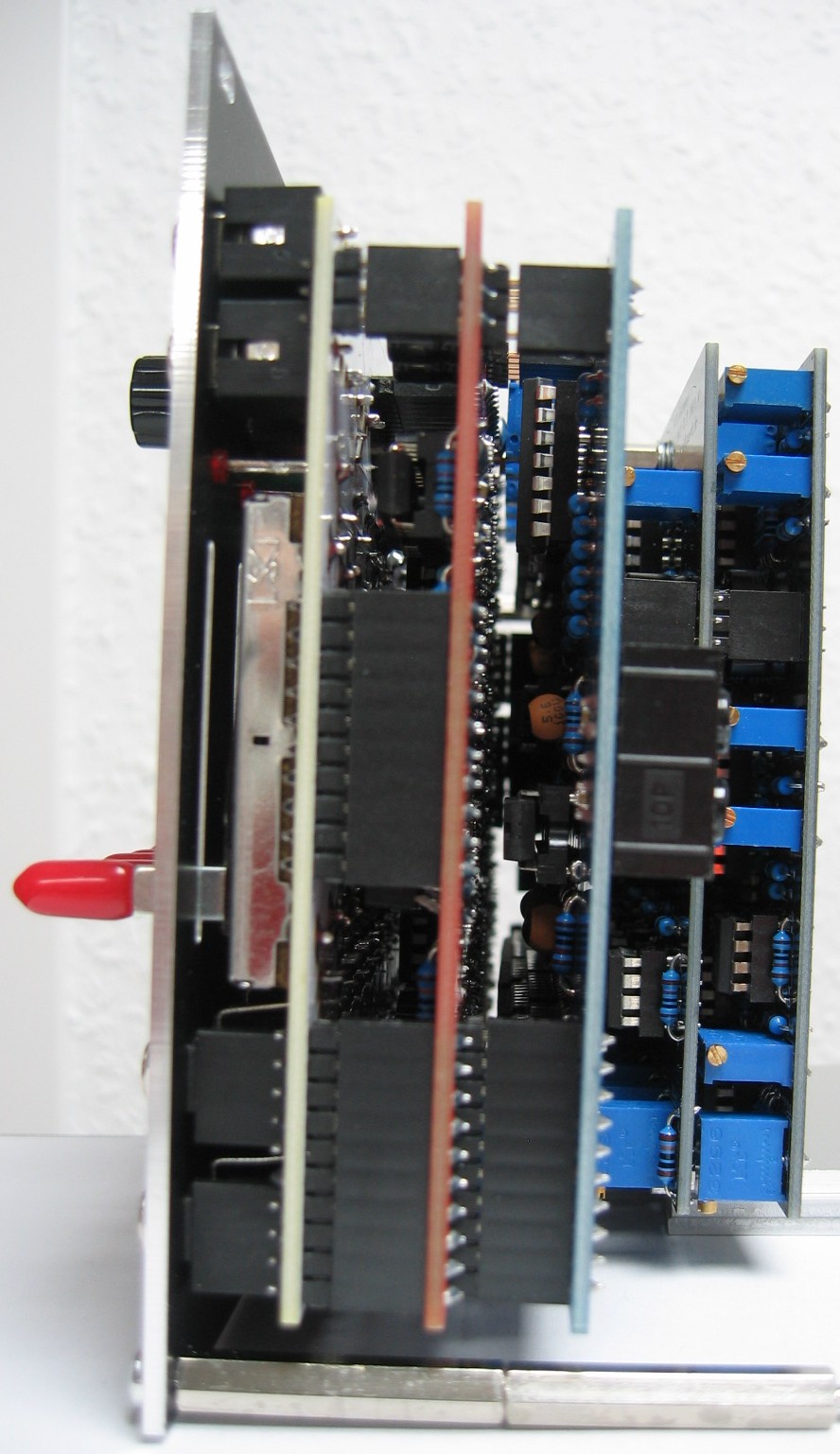
Harmonic Oscillator: Side view
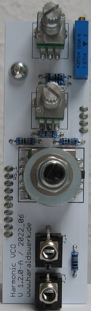
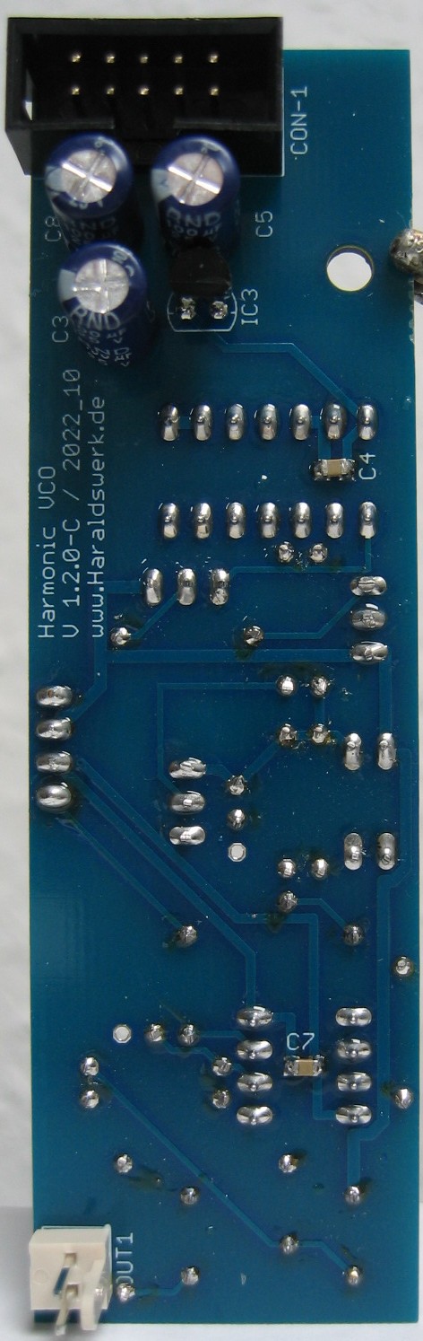
Harmonic Oscillator VCO: Populated control PCB
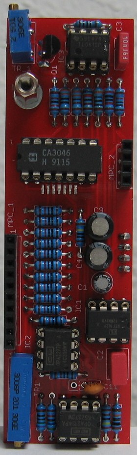
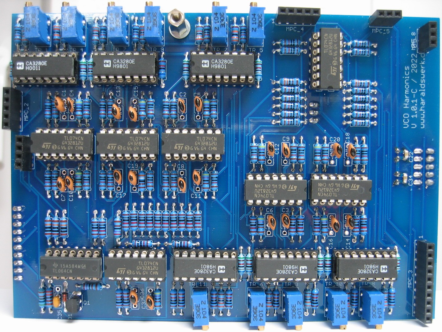
Harmonic Oscillator VCO: Populated main PCB 01
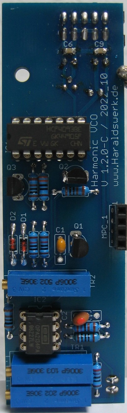
Harmonic Oscillator VCO: Populated main PCB 02 top