Motivation
This is one more module for my quad system. It contains four VCA with normalized input, so you can distribute one input signal to four output channels. With each channel under voltage control you can move the input signal through the room dependent on the control voltages. I have two versions build one AC and the other DC coupled. Beside using this VCA's for signal distribution you can use every VCA independently. The gain to voltage ratio is linear. This is done because it is easier to predict the performance. The distribution of the signal must be steered through the control voltages. The implementation follows the recommendations from an article at Open Music Labs from October 3, 2015 (Minimizing distortion in OTA's)
Specs and features
- Four VCA with normalized input
- Usable as four independent VCA as well
- Linear gain to voltage response
- Individual Volume, CV and Bias controls
- Low distortion implementation
- Runs on +/-12V and +/-15V (with minor resistor value changes for best performance)
- Power consumption around 35mA each rail
Implementation
Schematic

Quad VCA schematic: Main board 01

Quad VCA schematic: Main board 02
Description:
The linear controlled current source for Iabc is straight forward and implemented as usual. An elaborate description for the VCA part is given here

Quad VCA schematic: Control board DC

Quad VCA schematic: Control board AC
Description:
On the left side are the potentiometers for volume control followed by the input buffers. The only difference between AC and DC coupling are the capacitors. On the right side are the CV input potentiometers and the bias potentiometers followed by the voltage adder.
Calibration
- Zero adjust
- Set all potentiometers to zero.
- Measure the output at MP_1 (MP_2, MP_3, MP_4)
- Adjust trimmer TR_1 (TR_4, TR_7, TR_10) to zero Volt
- Second Harmonic
- Apply a sine wave of about 1kHz/10Vpp to the input
- Turn the volume and the bias all up
- Measure the THD and adjust TR_3 (TR_6, TR_9, TR_12) for lowest THD
- If you can't measure the second harmonic you can adjust the THD by eye and ear. Apply a 1kHz/10Vpp sine wave. Listen and have a look at your scope while adjusting the trimmer. The input and output sine should look the same on your scope and you should not here any distortion.
- Output DC offset (Only when DC coupled)
- Set volume and CV potentiometer to zero.
- Measure the output voltage while moving the bias potentiometer
- Adjust trimmer TR_2 (TR_5, TR_8, TR_11) so that the DC output swing is symmetrically to zero
Building hints
- The LM13700 differ in quality from part to part. You might want to select the IC for lowest DC output swing when DC coupling is used.
- Match capacitor C12 with C13 (C16 with C17, C20 with C21, C30 with C31)
Special parts
- None
Download
Quad VCA main board documentation downloadQuad VCA main board Gerber files download
Quad VCA AC control board documentation download
Quad VCA AC control board Gerber files download
Quad VCA DC control board documentation download
Quad VCA DC control board Gerber files download
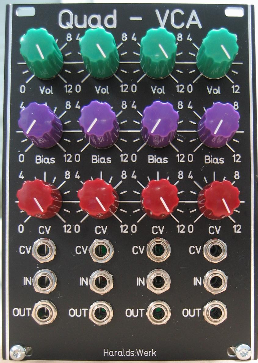
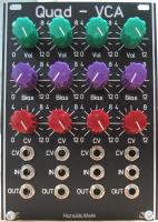
Quad VCA: Front view
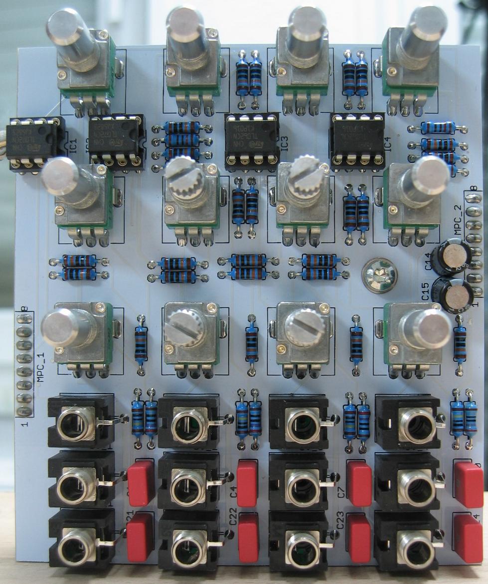
Quad VCA: Populated control PCB AC coupled
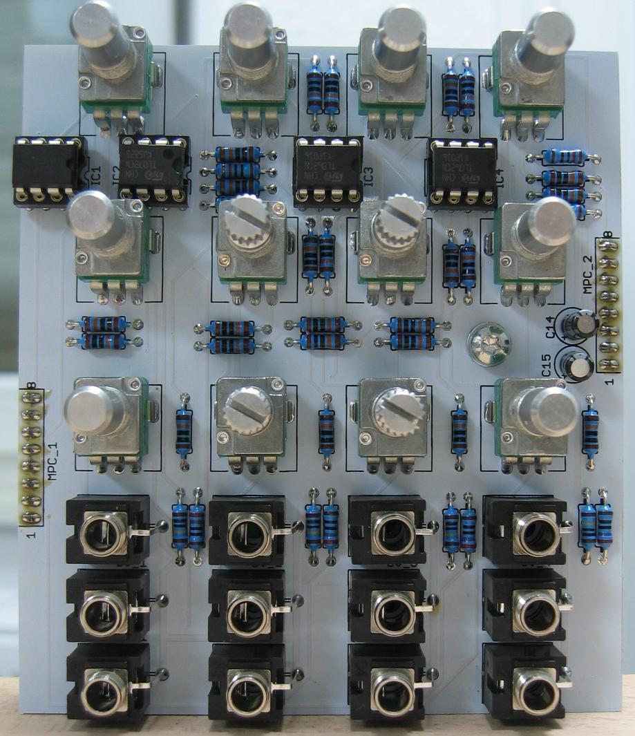
Quad VCA: Populated control PCB DC coupled
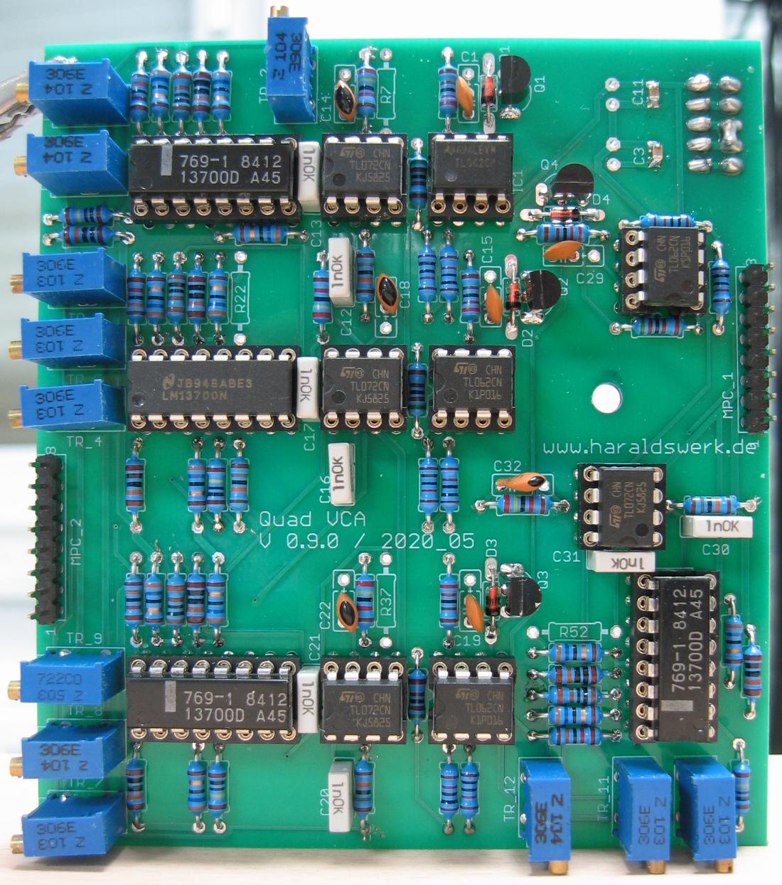
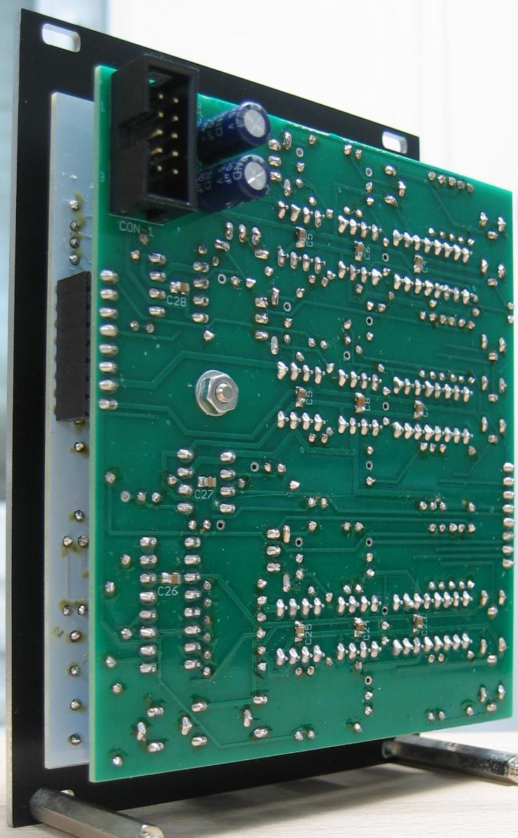
Quad VCA: Populated main PCB
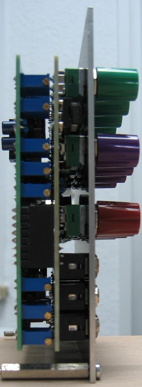
Quad VCA: Side view