Motivation

This utility module finds its usage in creating portamento and other slew limiting effects. The slew rate is controlled with a potentiometer. The slew states are controlled with two toggle switches. The first is a two state switch which toggles the slew function between lin mode or log mode. The second is a three state switch which sets the slew phases: Slew on rising edge only, slew on falling edge only or slew on rising and falling edge.
Specs and features
- Slew limiter on falling, rising or both edges.
- Lin or log mode.
- Runs on +/-12V and +/-15V
- Power consumption below 10mA each rail
Implementation
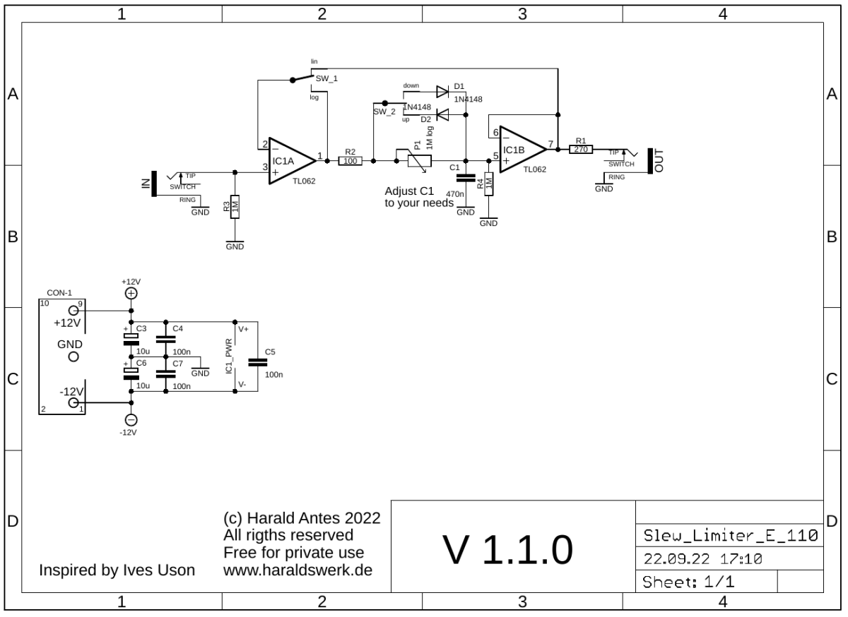
Schematic

Slew Limiter Euro: Schematic control board
Slew Limiter: screenshot slew up
Yellow line: input; Blue line: linear slew; purple line: exponential slew.
Slew Limiter: screenshot slew down
Yellow line: input; Blue line: linear slew; purple line: exponential slew.
Slew Limiter: screenshot slew up/down
Yellow line: input; Blue line: linear slew; purple line: exponential slew.
Description:
Log mode: In log mode IC1A is a simple voltage follower. With SW_2 in middle position the output of IC1A charges or discharges C1, depending on the voltage level, through R2 and P1. The time constant depends on the setting of P1. IC1B buffers the output of C1. If we toggle SW_2 up or down one of the diodes is bypassed. Then the charging or discharging only depends on R2 and becomes very fast on the up or down slope.
Lin mode: In lin mode IC1A is controlled by the input voltage and the output voltage. The output voltage is fed back to the negative input of IC1A. In this configuration the charge/discharge current of C1 is kept constant. Because the current is constant the charging/discharging curve remains linear.
Calibration
- None
Building hints
- None
Special parts
- None
Download
Slew Limiter Euro control board documentation downloadSlew Limiter Euro control board Gerber files download
Slew Limiter Euro *.fpd file