VC Toggle Switch 1 in 2 buffered

Motivation

VC controlled toggle switch front

Not much to say. Just a unidirectional toggle switch. The input is switched between two buffered outputs. Voltage and manually controlled. Status signaled with LED.


Specs and features


Implementation

Schematic

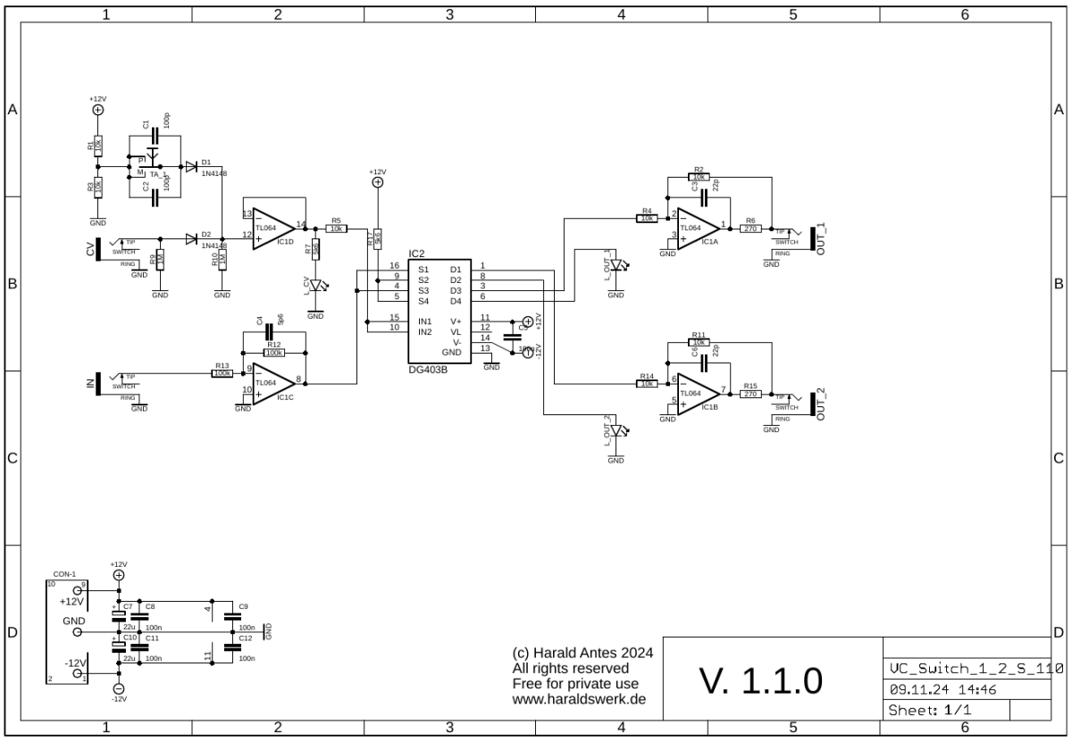
Voltage controlled toggle switch schematic control board

Voltage controlled toggle switch 1 in 2: Schematic control board

Description:

The interesting point here is the overvoltage protection for the control voltage input. This is done with the MCP6002 rail to rail operational amplifier. He is powered between GND and +5V. So, no negative or positve voltage above +5V will go through it. The diode in the input is not needed for voltage protection. The diode protects the voltage source when it supplies a negative voltage. Without the diode the negative signal is loaded by the input of the MCP600x. The 1M resistors are there to provide a defined potential.


Top

Calibration

  • None
Top

Building hints

  • None

Special parts

  • You want to use the DG403 with the voltage range +/-15V. Check the datasheet. There are lower rated ones.

Download

VC Toggle Switch control board documentation download
VC Toggle Switch control board Gerber files download
VC Toggle Switch *.fpd file

VC Toggle Switch front view

VC Toggle Switch: Front view


VC Toggle Switch populated control PCB front

VC Toggle Switch: Populated control PCB front


VC Toggle Switch populated control PCB back

VC Toggle Switch: Populated control PCB back


VC Toggle Switch halve side view

VC Toggle Switch: Halve side


VC Toggle Switch halve back view

VC Toggle Switch: Halve back


VC Toggle Switch side view

VC Toggle Switch: Side view


2024 November

Top Home