Motivation

Here is the pitch 2 voltage converter for my Shakuhachi 2 Synth project. It is based on an article in Electronotes EN#84 p5-p9 from Robert Iodice. It consist of some control logic and a 12bit DA converter. I have found a fault in the control logic and simplified the DA converter. The original only had a V/Hz output, so I added a V/Oct output..
The circuitry takes a pulsetrain and converts it to a voltage according to the frequency of the pulsetrain.
The circuit has the advantage of sampling very quickly (only two pulses required) and holding indefinitely.
Specs and features
- Input pulsetrain 5V
- Output voltage V/Oct and V/Hz
- Very quick sampling
- Output voltage holds indefinitely
- Runs on +/-15V and +/-12V (with minor resistor value changes)
- Schematic pitch 2 votage converter
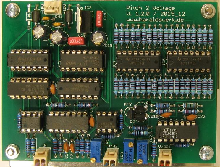
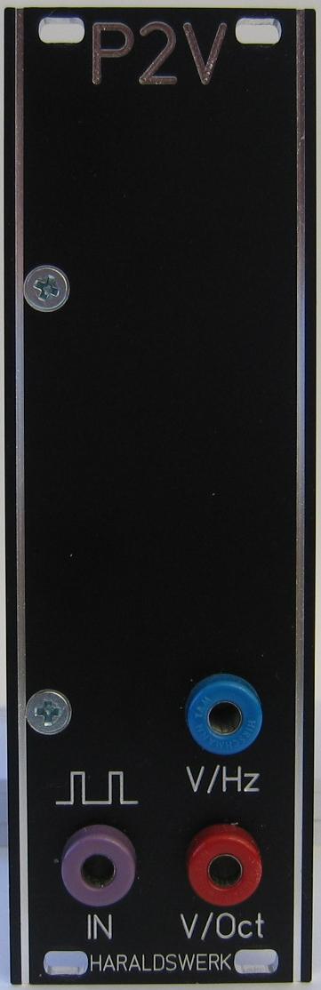
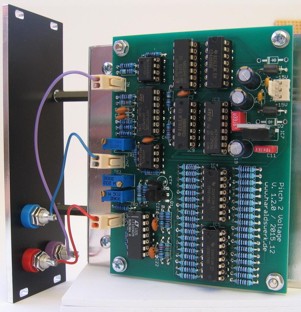
- Pictures
- Download docs
Implementation
Schematic
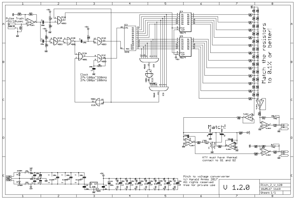
Pitch 2 voltage converter: Schematic
Description:
A clock of about 320kHz (4093 IC1C) is used to drive a 12bit binary counter (4040). The outputs of which are fed through latches (40174) and then to a 12-bit DA converter (R2R). The voltage is then converted to V/Oct characteristic with a anti-log generator (National AN30 p4 fig3). The additional circuitry is to control the timing sequence, gating the clock signal and generating a flag signal. The flag is generated when the outputs of the counter all reach a high level(4068). This condition is reached when the input is removed or the input frequency drops below the systems lower frequency limit.
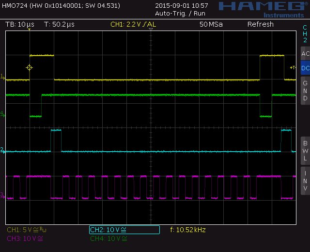
Pitch 2 voltage converter: Timing diagram
Calibration
- V/Oct output: Apply a pulse train of a certain frequency with +5V/10us minimum to the input. Measure the ouptut voltage V1. Double the frequency. Measure the output voltage V2. The difference between V1 and V2 should be one volt. Adjust TR3. Repeat.
Special parts
None
Building hints
Match Q1 and Q2. Glue them together for thermal contact. Same with KTY.
Match the resistors in the R2R ladder to 0,1% or better.