Motivation

This is my take on the VCA. Because this one is for my Next Generation Formant project i started with the original Elektor Formant VCA schematic and added my changes to the design. All parts are updated to today (2017/08) available parts. The connections are the same as in the original to keep the possibility for internal wiring. If you don't need those features just leave them out. This PCB provides all functions as in the original Elektor Formant VCA. The CA3080 are replaced with LM13700. The signal level is raised to 10Vpp for a better signal to noise ratio. The added volume indicator us useful for finding the appropriate signal level. The volume indicator is optional. You can leave it out with no problems for the other functions.
Specs and features
- VCA log and lin response in series configuration
- 10Vpp signal level
- ENV input 0..5V
- AM input -5v...+5V
- Volume indicator
- Runs on +/-15V and +/-12V (with minor resistor value changes)
- Schematic VCA
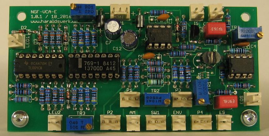
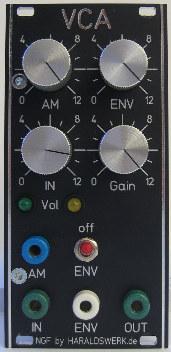
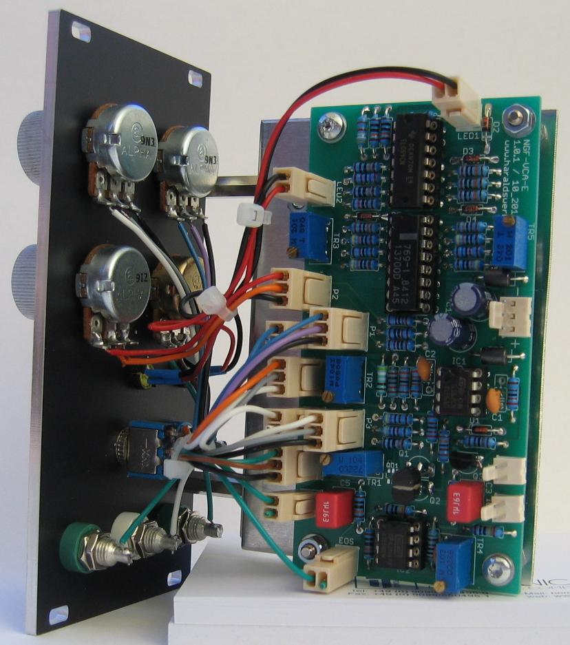
- Pictures
- Download docs
Implementation
Schematic
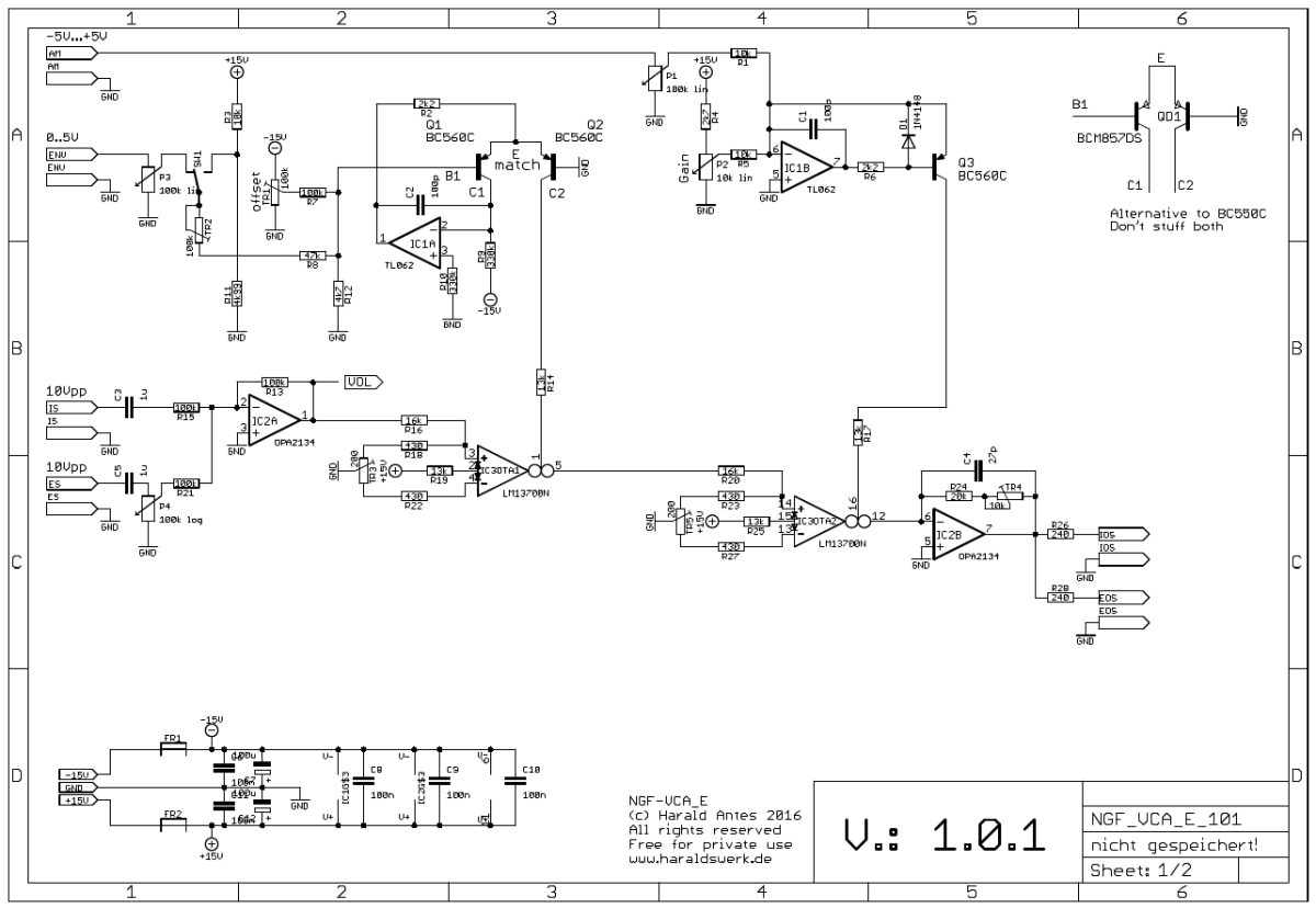
NGF-E VCA schematic 01 (main)
Description:
This is a close clone of the Elektor Formant VCA. It consists off two OTA's in serial configuration. The first OTA provides the log response and the second one the linear response. IC2A sums up the external and internal audio signal. The circuitry around IC1A provides the log converter, IC1B the linear current source for the second OTA.
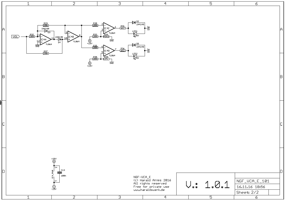
NGF-E VCA schematic 02 (level display)
Description:
Nothing special here. Just a PVWR and two comparators
TopCalibration
Stage one OTA
- Move whipper of TR1 to ground.
- Set switch SW1 to ENV
- Apply signal of about 1kHz/10Vpp to input
- Look at pin 5 of the first OTA (IC3DTA1) with oscilloscope (signal is at 180deg phase).
- Adjust TR1 to minimal signal feedthrough (~-3.5V at whipper).
- Set swithc SW1 to off
- Adjust TR2 so that the volume of the signal at pin5 is near the input signal 180deg phase).
- Set scope to DC
- Adjust TR3 for minimum DC offset
Stage two OTA
- Connect oscilloscope to output.
- Set gain potentiometer to max.
- Adjust TR4 to equal volume for the output signal with the input.
- Adjust TR5 for minimum DC offset.
Special parts
None
Match Q1 and Q2 and glue them together for best results. Or use the BCM857