Motivation

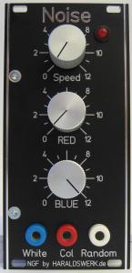
This is the noise module for my Next Generation Formant project. It is a combination of two original Elektor Formant modules. The Noise module from Elektor Formant book one and the Coloured Noise (CNC) module from book two. It provides a white noise output, a fixed coloured noise output, a variable coloured noise output "red" "blue" and a random voltage output. The noise is derived from the reverse biased BE diode of an NPN transistor.
Specs and features
- Noise source: BE diode from a NPN transistor
- White noise output
- Fixed coloured noise output
- Variable coloured noise output "red" and "blue"
- Random voltage output
- Runs on +/-15V and +/-12V (with minor resistor value changes)
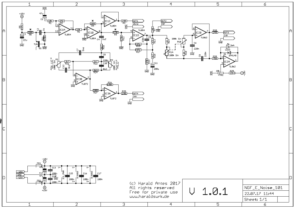
- Schematic NGF-E Coloured Noise / Random Voltage
- Pictures
- Download docs
Implementation
Schematic

NGF-E: Coloured Noise / Random Voltage
Description:
Noise source is the reverse biased BE diode of NPN transistor Q1. The following operational amplifier IC1A and IC1B amplifies the noise to 10Vpp. IC1C is the buffer for the white noise output. The high pass filter C5/R23 and R13/R19 in the feedback loop of IC1D provides a bass boost for the fixed coloured noise output. IC2B is configured as a 12dB low pass. So you get a low frequency random voltage. The changing speed is set with P1A/P1B which sets the corner frequency of the low pass filter. IC2A / LED1 makes the fluctuation visible. Tr1 adjust the brightness of LED1. In the feedback loop of IC3B is an adjustable filter combination which gives you a wide range of adjustable coloured noise with P1 and P2. The output is buffered with IC3A.
TopCalibration
- If the transistor is not "noisy" enough you can try changing R8. Useful are values between 30k and 150k.
- Adjust R4 for your wanted white noise output level.
- Adjust R9 so that the output level of the fixed coloured noise output equals the white noise output
- Adjust TR1 for best visibility of the fluctuation of random voltage
Special parts
None. But it might be useful to select the noisiest transistor you have at hand