Motivation
This is my take on the 24dB HP/LP VCF. This filter type is widely used in many synthesizers. Because this one is for my Next Generation Formant project i started with the original Elektor Formant schematic and added my changes to the design. All parts are updated to today (2017/7) available parts. The connections are the same as in the original to keep the possibility for internal wiring. If you don't need those features just leave them out. This PCB provides all basic functions as in the original Elektor Formant. The additional functionality is put on an add-on board. The CA3080 are replaced with LM13700. The LP/HP switch is replaced with DG419 to avoid wiring problems. The signal level is raised to 10Vpp for a better signal to noise ratio. The exponentiator for generating Iabc for the OTA's is temperature compensated. The additional function on this PCB is the linear TM input and the sign changer for the ENV input for easier use when the filter is switched to high pass mode. All other additional functions are on the add-on board.
The add-on board provides voltage control for Q and the volume indicator.
Specs and features
- 24dB highpass filter, 24dB lowpass filter
- Temperature compensated exponentiator
- 10Vpp signal level
- TM log input
- TM lin input
- Positive and negative ENV control with sign changer
- Volume display (with AddOn PCB)
- Voltage controlled Q (with AddOn PCB)
- Runs on +/-15V and +/-12V (with minor resistor value changes)
- Schematic 24dB LP/HP VCF
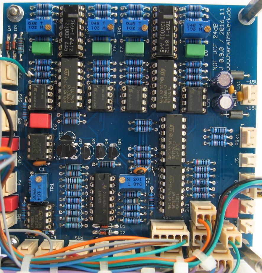
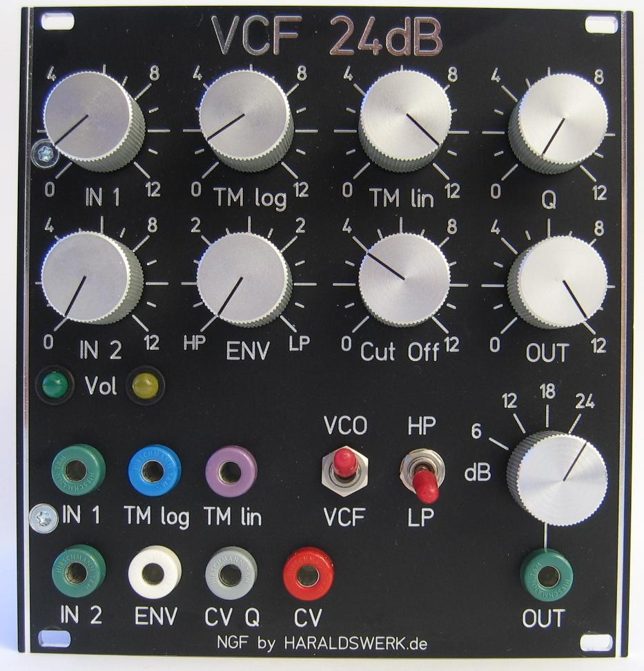
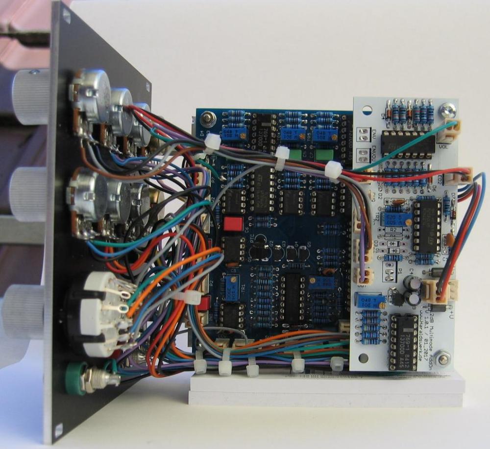
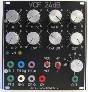
- Pictures
- Download docs
Implementation
Schematic
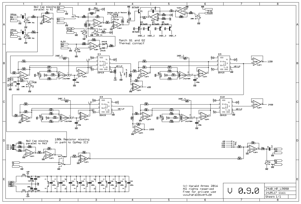
NGF E 24dB HP/LP VCF schematic
Description:
There are a lot descriptions of those state variable filters out there. I feel no need to add another one. On the lower part of the schematic you can see the additional circuitry which is needed if you want to use Elektor Formant wiring option.
TopCalibration
DC offset OTA
- Remove IC3, IC6 and the DG419 IC4, IC5, IC 9, IC10
- (OTA1 = IC7OTA1) Attach a 10k resistor from pin5 IC6D to ground (Just stick it in the IC socket).
- (OTA1 = IC7OTA1) Turn Cut Off potentiometer full on.
- (OTA1 = IC7OTA1) Measure the voltage at pin5 IC6D. Adjust to zero with TR3
- (OTA2 = IC7OTA2) Attach a 10k resistor from pin10 IC6B to ground(Just stick it in the IC socket) .
- (OTA2 = IC7OTA2) Turn Cut Off potentiometer full on.
- (OTA2 = IC7OTA2) Measure the voltage at pin10 IC6D. Adjust to zero with TR4
- (OTA3 = IC12OTA1) Attach a 10k resistor from pin5 IC11D to ground (Just stick it in the IC socket).
- (OTA3 = IC12OTA1) Turn Cut Off potentiometer full on.
- (OTA3 = IC12OTA1) Measure the voltage at pin5 IC11D. Adjust to zero with TR5
- (OTA4 = IC12OTA2) Attach a 10k resistor from pin10 IC11B to ground (Just stick it in the IC socket).
- (OTA4 = IC12OTA2) Turn Cut Off potentiometer full on.
- (OTA4 = IC12OTA2) Measure the voltage at pin10 IC11D. Adjust to zero with TR6
- Remove resistor and put the IC's back in
Cut Off
- Apply a square signal of about 500Hz to the input. Set the filter to lowpass mode.
- Set potentiometer P4 (Cut off) to max (15V). Set trimmer TR1 to ground.
- Turn TR1 slowly to -15V. You will see and hear that the edges of the square signal starts rounding.
- Adjust TR1 so that there is no audible damping of the overtones. This adjustment is not critical. No need for excessive precision.
V/Octave
- Measure the voltage at the basis off transistor Q1. If you change the voltage at the KOV input 1V, the voltage at the basis of the transistor Q1 should change about 17mV. Adjust with TR2
Special parts
None
For best result match the OTA's for Gm