Motivation
This is my take on a pan and scan mixer with 4 channels. The module provides a 4 channel mixer with voltage control over level, panning and spread of the channels. The spread is a unique feature which allows to adjust the separation between the channels. You can scan through the channels manually or with external voltage. The depth and starting position is adjustable as well.
Specs and features
- 4 channel mixer
- Manual and voltage controlled volume per channel
- Manual and voltage controlled pan per channel
- Manual and voltage controlled scan
- Manual and voltage controlled spread
- Left and right out
- Power consumption around 180mA each rail
Implementation
Schematic

Pan and Scan schematic: Control board

Pan and Scan schematic: Main board B/01

Pan and Scan schematic: Main board B/02

Pan and Scan schematic: Main board C/01

Pan and Scan schematic: Main board C/02

Pan and Scan schematic: Main board C/03

Pan and Scan schematic: Main board D/01

Pan and Scan schematic: Main board D/02
Description:
This is a combination of a voltage controlled scanner with VCA. The scanner part is derived from the work of Juergen Haible and Don Tillman. The VCA for the scanning part have exponential response the volume VCA are linear controlled.
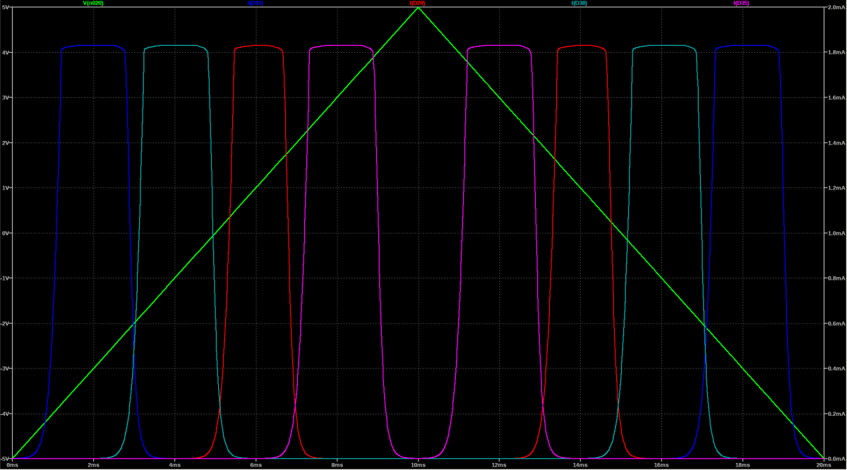
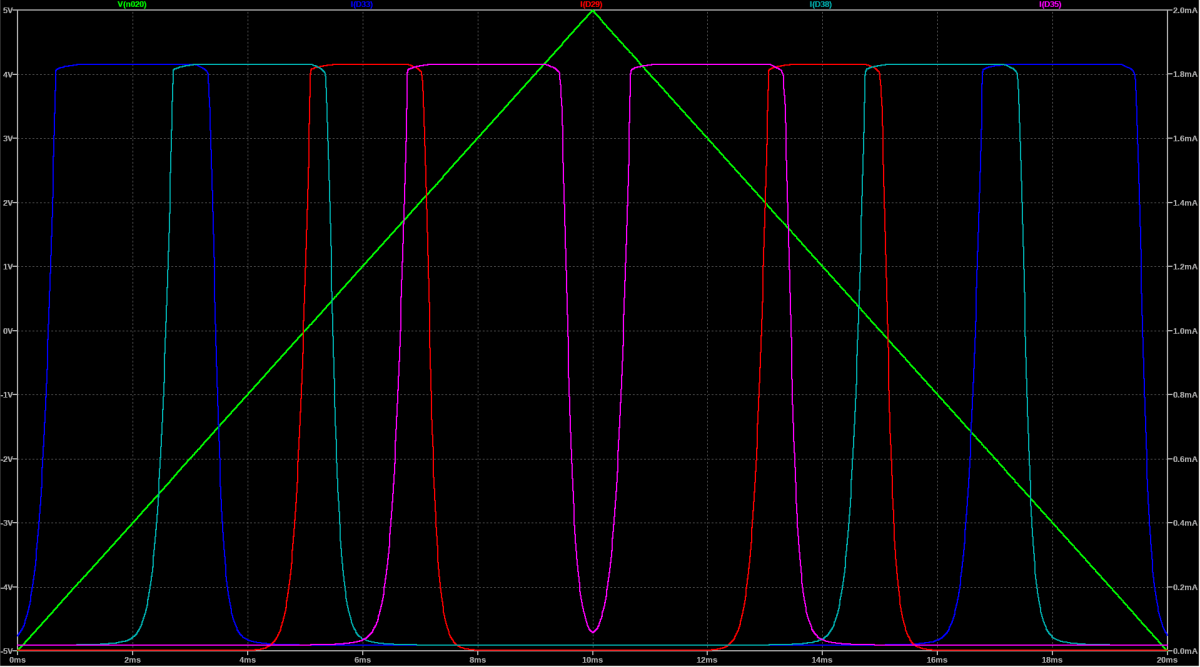
Below you can see what the "Spread" potentiometer and CV is for. The green line shows the scan voltage, the other lines shows the Iabc through the OTA's, which is equal to the loudness you hear. From top down the setting of the "Spread" potentiometer is increased from zero to max. You can see that the gap between the channels gets smaller and small and then start to overlap until the channels stay open. This parameter is voltage controllable as well.
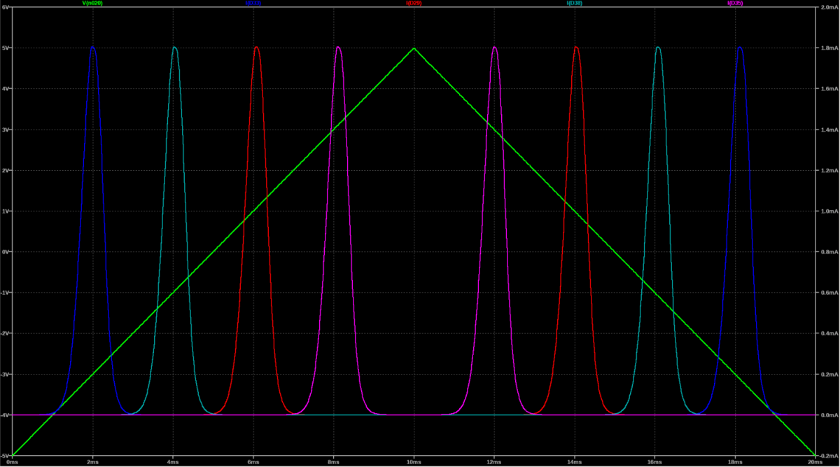
Pan and Scan channel gap/overlap: Max gap
Pan and Scan channel gap/overlap: Middle gap
Pan and Scan channel gap/overlap: No gap
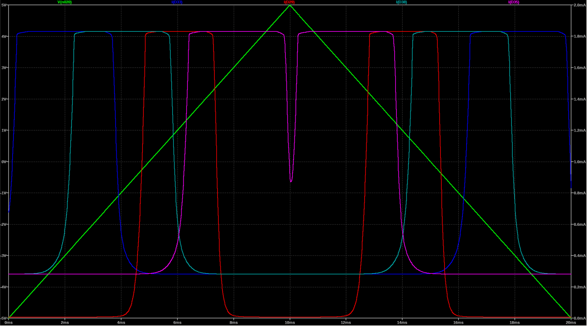
Pan and Scan channel gap/overlap: Overlap
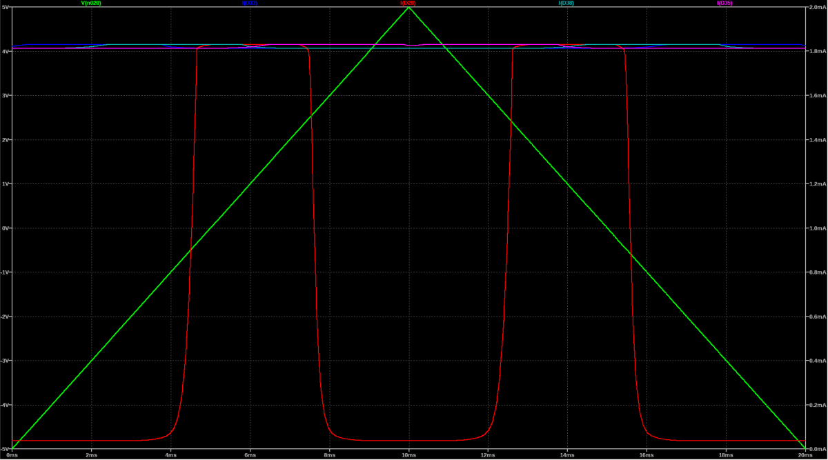
Pan and Scan channel gap/overlap: Max Overlap
Calibration
First make a gross function test. All in and outs should work as expected and all potentiometer and sliders have some effect.
Connect a scope to the left and right output. DC coupled. You'll need this to adjust the DC offset of the OTA's.
- Pan OTA DC offset channel one
- Remove both OTA IC2 and IC4 from board C.
- Remove OTA IC8 from board C.
- Remove OTA IC2 and IC5 from board D
- Set pan pot channel one to max left
- Adjust TR_5 (board C) to zero Volt for left channel.
- Set pan pot channel one to max right
- Adjust TR_6 (board C) to zero Volt for right channel.
- Pan OTA DC offset channel two
- Remove OTA IC6 from board C.
- Put OTA IC8 back in board C.
- Set pan pot channel two to max left
- Adjust TR_7 (board C) to zero Volt for left channel.
- Set pan pot channel two to max right
- Adjust TR_8 (board C) to zero Volt for right channel.
- Pan OTA DC offset channel three
- Remove OTA IC8 from board C.
- Put OTA IC2 back in board D.
- Set pan pot channel three to max left
- Adjust TR_1 (board D) to zero Volt for left channel.
- Set pan pot channel three to max right
- Adjust TR_2 (board D) to zero Volt for right channel.
- Pan OTA DC offset channel four
- Remove OTA IC2 from board D.
- Put OTA IC5 back in board D.
- Set pan pot channel four to max left
- Adjust TR_3 (board D) to zero Volt for left channel.
- Set pan pot channel four to max right
- Adjust TR_4 (board D) to zero Volt for right channel.
- Volume OTA DC offset
- Put all OTA back in.
- Set pan pot channels to center.
- Set volume slider channel one to max
- Adjust TR_1 (board C) to zero Volt for left and right channel.
- Set volume slider channel one to min
- Set volume slider channel two to max
- Adjust TR_2 (board C) to zero Volt for left and right channel.
- Set volume slider channel two to min
- Continue with channel three and four accordingly
Building hints
- None
Special parts
- Instead of the here used CA3280 (I am using up some NOS) you can use the new available AS3280.
- The sliders are from Befaco (Thonk or Befaco)
- The connectors are Thonkicons (Thonk)
Download
Pan and Scan control board documentation downloadPan and Scan control board Gerber files download
Pan and Scan main board B documentation download
Pan and Scan main board B Gerber files download
Pan and Scan main board C documentation download
Pan and Scan main board C Gerber files download
Pan and Scan main board D documentation download
Pan and Scan main board D Gerber files download
Pan and Scan *.fpd file
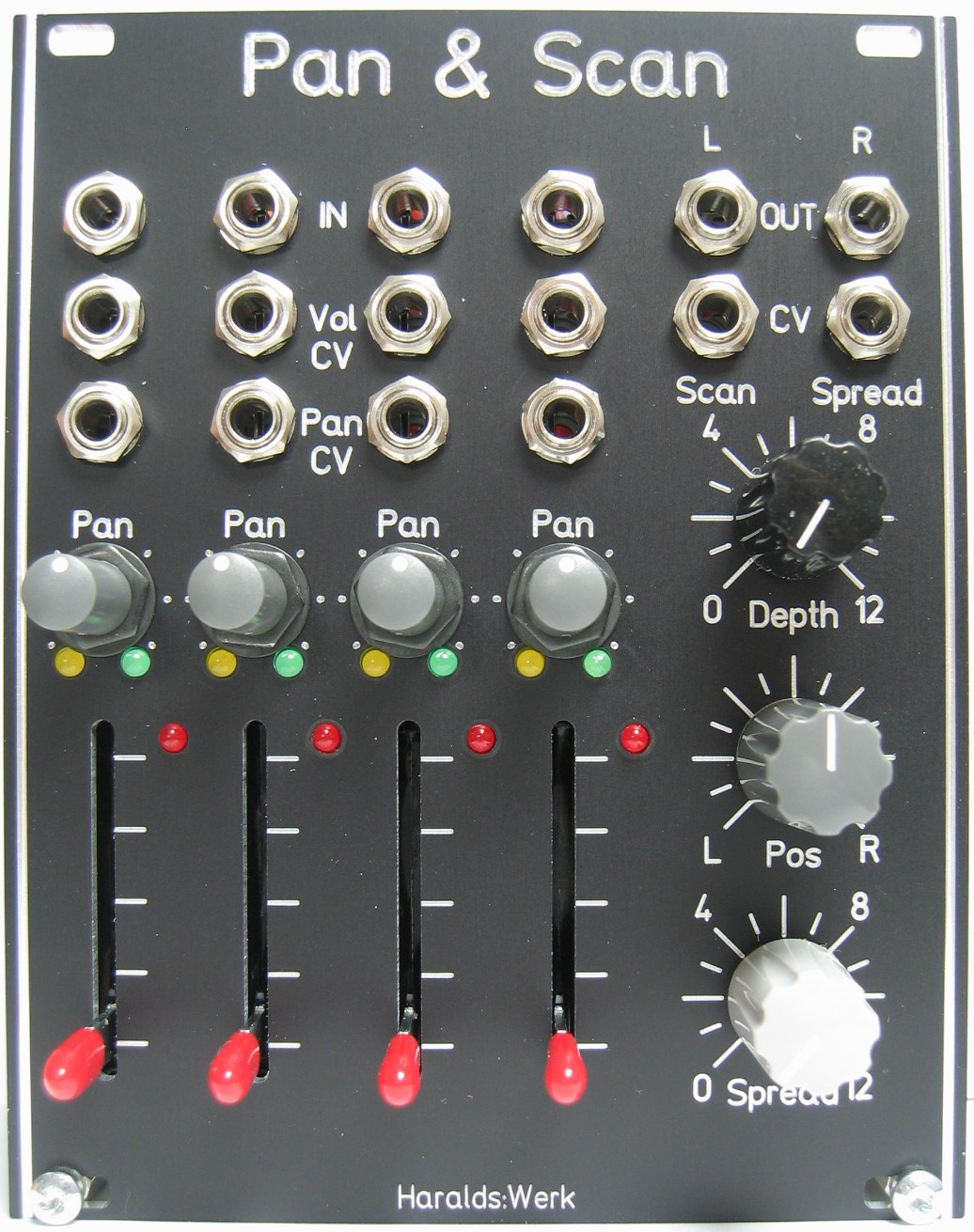
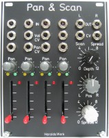
Pan and Scan: Front view
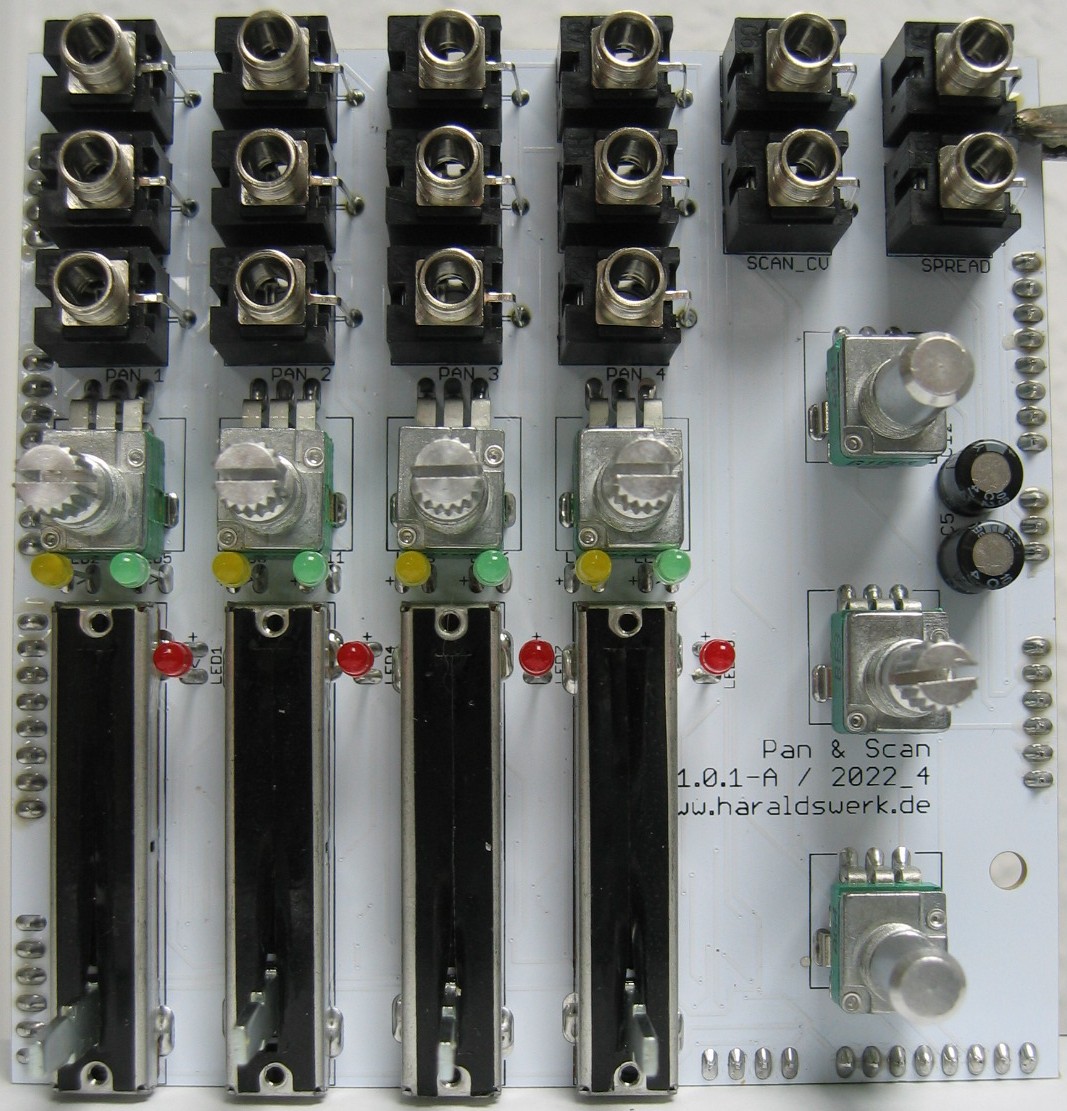
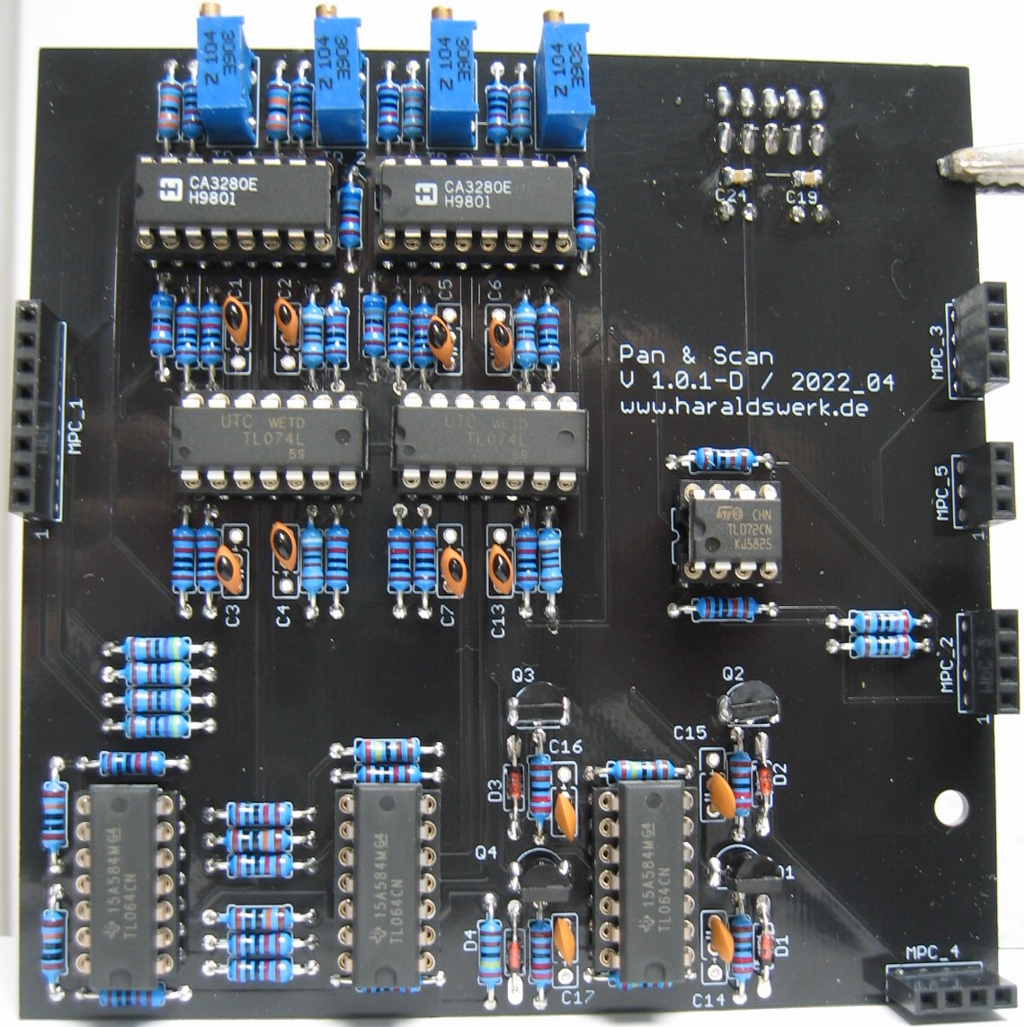
Pan and Scan: Populated control PCB top
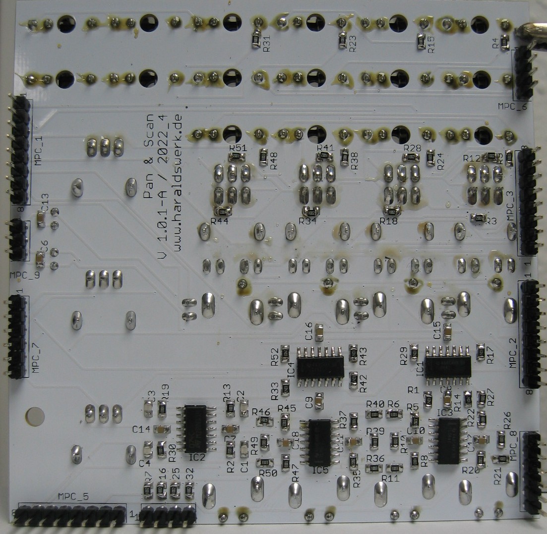
Pan and Scan: Populated control PCB back
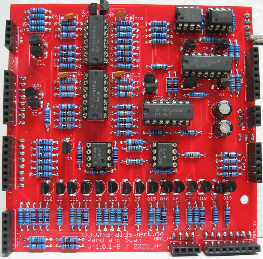
Pan and Scan: Populated main PCB B
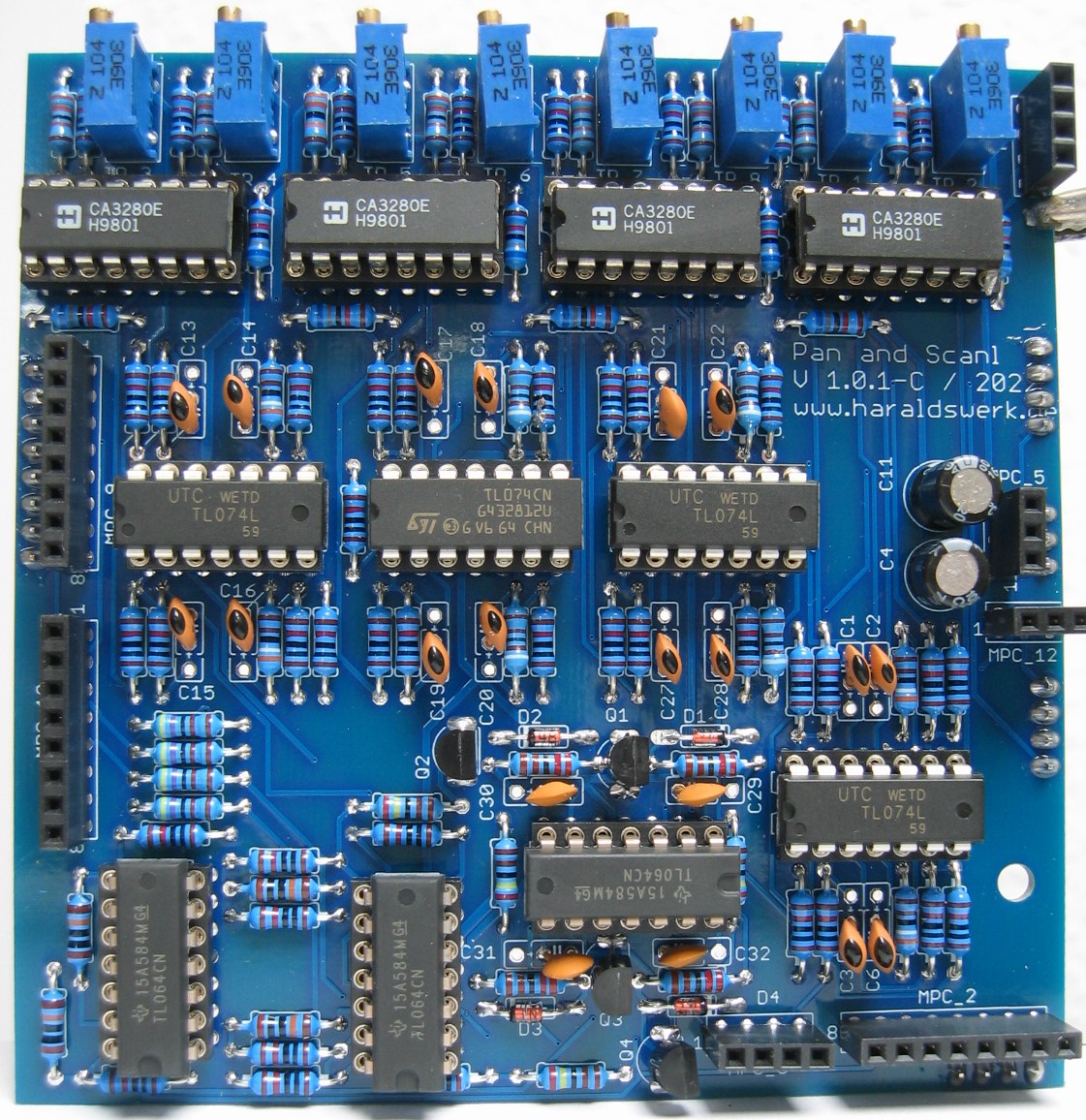
Pan and Scan: Populated main PCB C
Pan and Scan: Populated main PCB D
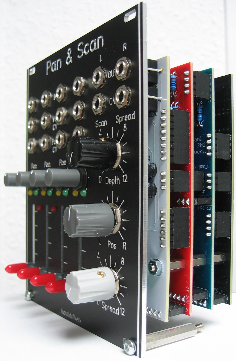
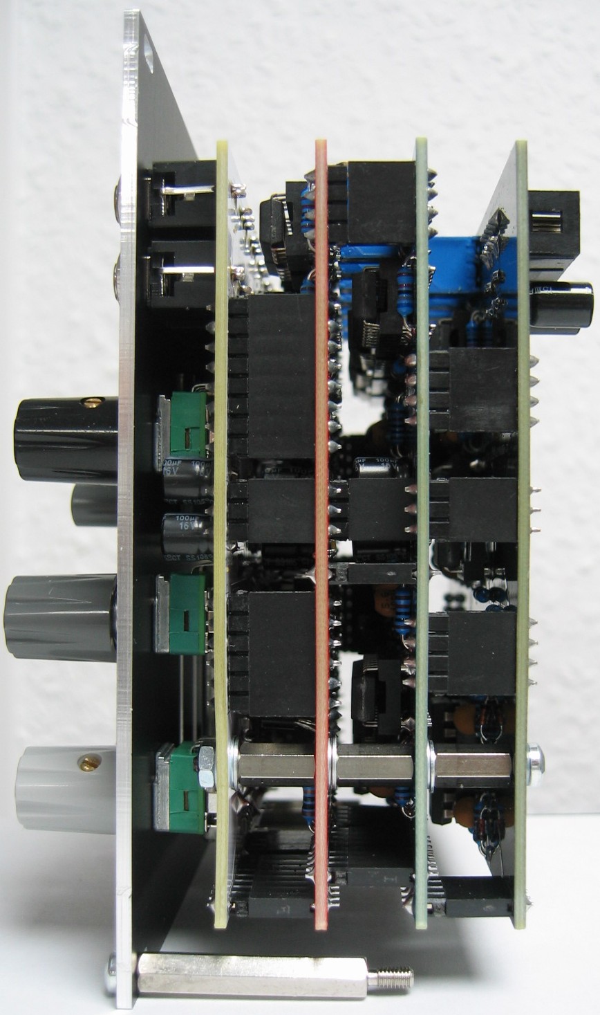
Pan and Scan: Half front view