Motivation

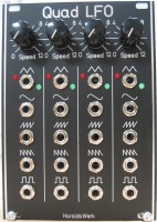
Four independent LFO with triangle, sine, ramp up, ramp down and square wave output. Output voltage 10Vpp. The sine is inverted against the triangle. Ramp up and ramp down are twice the frequency of the triangle.
Specs and features
- Four independent LFO
- Triangle, sine, ramp up, ramp down and square wave output
- Output -5V to +5V (10Vpp)
- Runs on +/-12V
- Power consumption below 25mA each rail
Implementation
Schematic

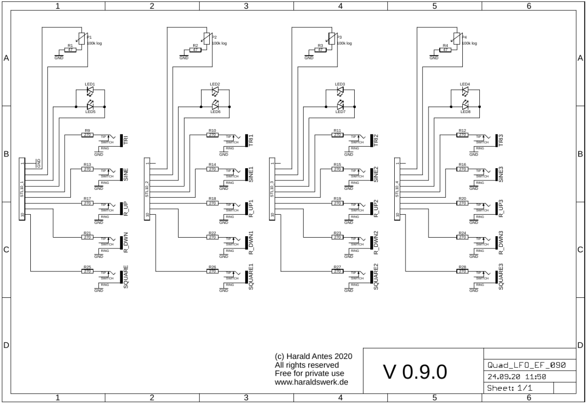
Quad LFO schematic: Control board

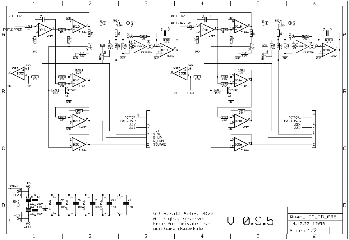
Quad LFO schematic: Main board 01

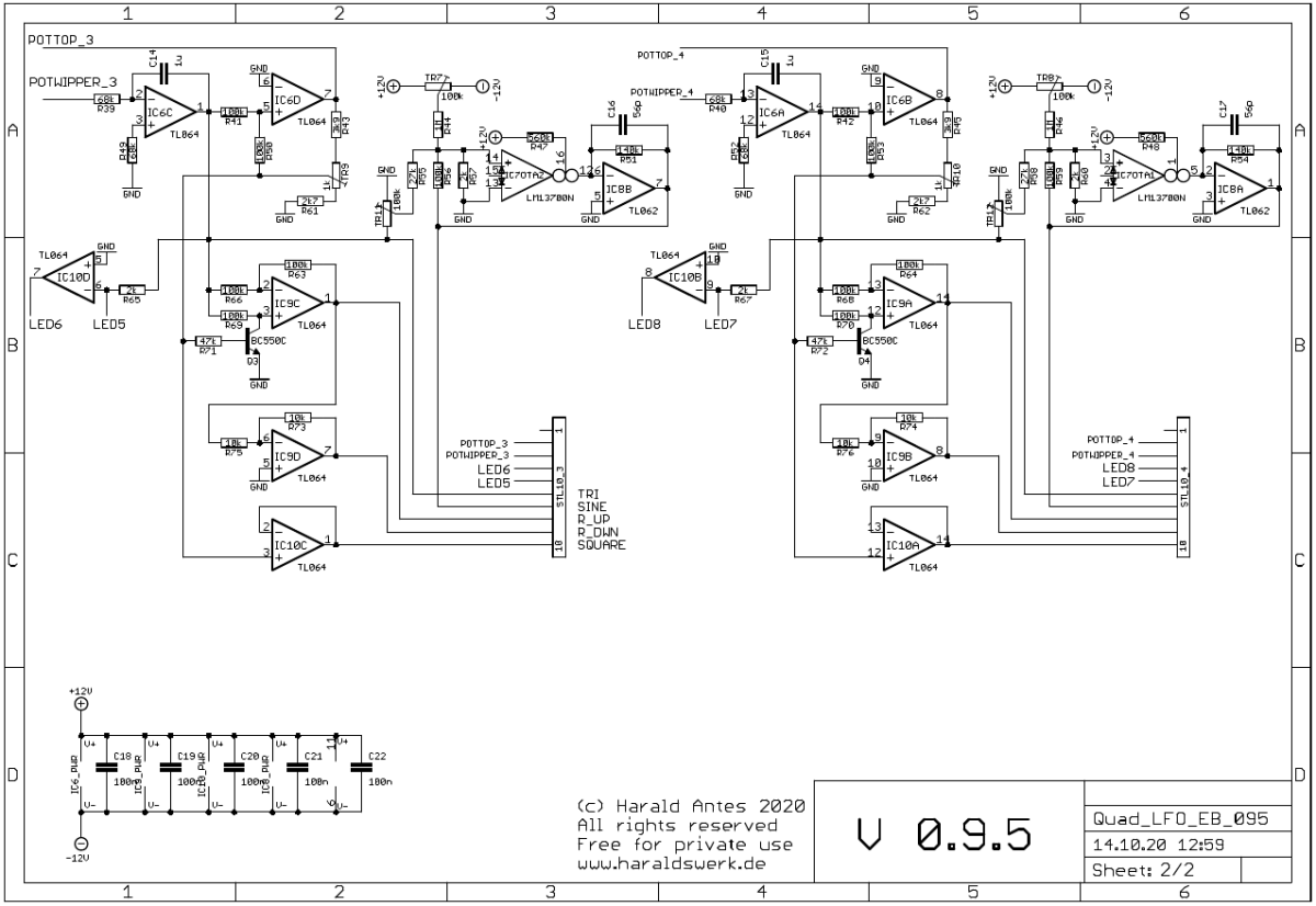
Quad LFO schematic: Main board 02
Description:
Given for the first LFO. The oscillator consists of an integrator IC1C and an OpAmp Schmitt-Trigger IC1D. The triangle wave of the oscillator arises through the feedback of the trigger output to the input of the integrator. At the integrator output IC1C arises a triangle with the amplitude of the hysteresis of the Schmitt-Trigger. The input voltage of the integrator sets the rise and fall time of the voltage output. The square wave output is buffered with IC5C. The circuitry around IC4C provides the saw output. IC4D inverts the saw. The sine shaper is build with the OTA IC2OTA2 and IC3B. IC5D drives the LED.
Quad LFO: Screenshot 01
Quad LFO: Screenshot 02
Note:
The sine is inverted against the triangle. Ramp up and ramp down are twice the frequency of the triangle.
Calibration
- Output level
- Set TR3 (TR4, TR9, TR10) to 5Vpp output level
- Sine wave
- Adjust TR5 (TR6, TR11, TR12) until the edges of the triangle rounds off to a sine.
- Adjust TR1 (TR2, TR7, TR8) for zero offset.
Building hints
- For different frequency ranges use different capacitors for C1, C2, C14, C15
Special parts
- None
Download
Quad LFO main board documentation downloadQuad LFO main board Gerber files download
Quad LFO control board documentation download
Quad LFO control board Gerber files download