Motivation
This module takes the incoming gate or trigger and routes it to either of its two outputs. The distribution is software driven, according to a random coin toss. You can select the probability distribution with a potentiometer and an input control voltage. The potentiometer voltage and the control voltage are added together. The probability goes from 0% to 100% at output A and from 100% to 0% on output B.
Specs and features
- Randomly skip Gates and Triggers
- Voltage controlled probability distribution
- Dual Bernoulli gate
- Runs on +/-12V and +/-15V
- Power consumption below 20mA positive rail. 5mA negative rail.
Implementation
Schematic

Bernoulli Gate: Schematic control board

Bernoulli Gate: Schematic main board
Description:
Nothing special to mention. On page one you see the output buffers. On page two are the input protection circuitry and the micros.
Calibration
- None
Building hints
- None
Special parts
- None
Download
Bernoulli Gate control board documentation downloadBernoulli Gate control board Gerber files download
Bernoulli Gate main board documentation download
Bernoulli Gate main board Gerber files download
Bernoulli Gate software files download
Bernoulli Gate *.fpd file
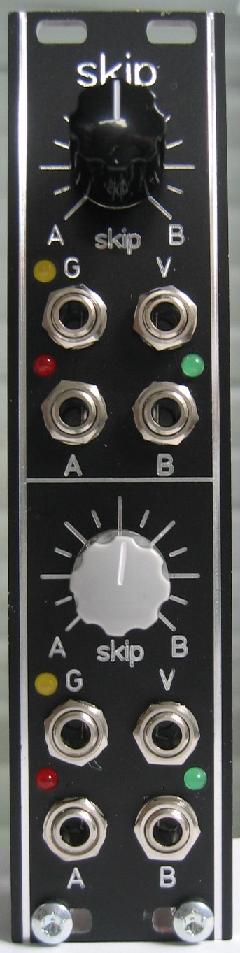
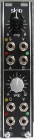
Bernoulli Gate: Front view
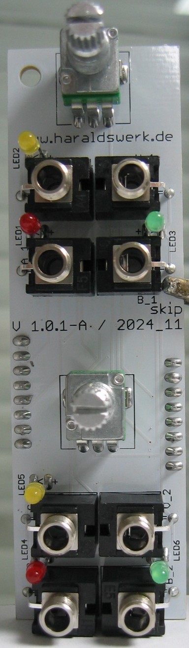
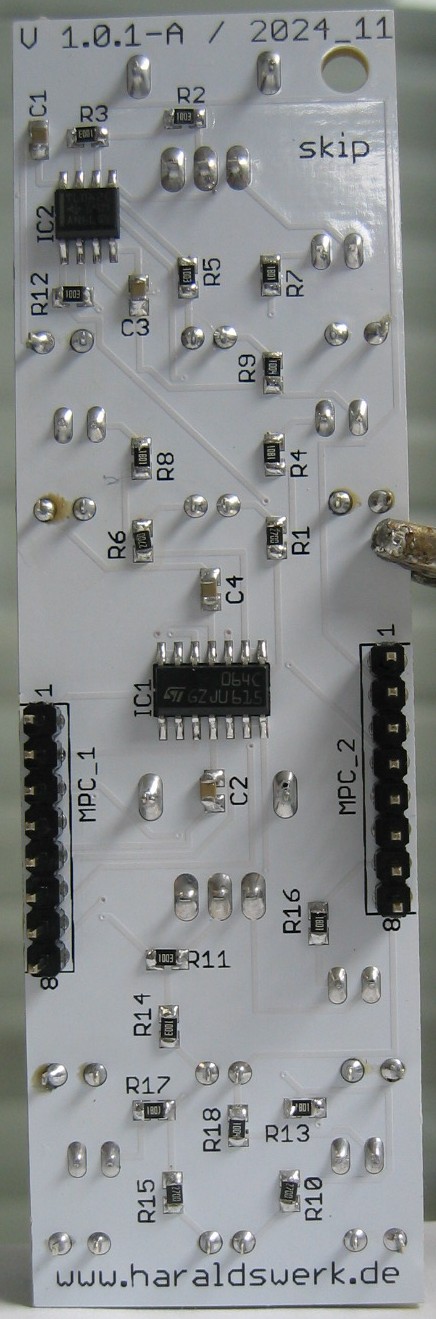
Bernoulli Gate: Populated control PCB top
Bernoulli Gate: Populated control PCB back
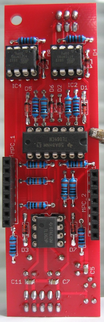
Bernoulli Gate: Populated main PCB top
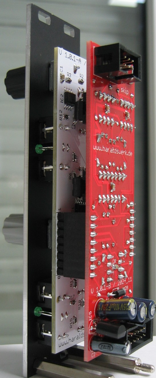
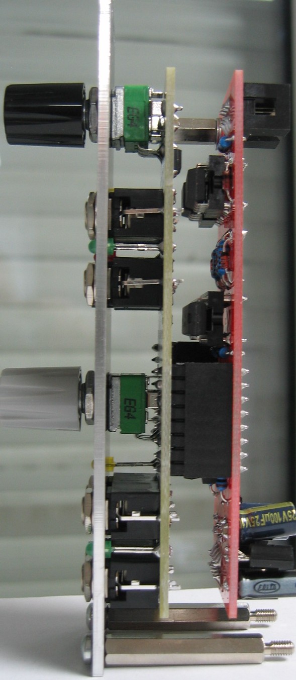
Bernoulli Gate: Back view