Motivation
With this module you can distribute the incoming gate or trigger up to eight outputs. The distribution is software driven. You can select the amount of the stepped through outputs from zero to eight with a potentiometer and an input control voltage. The potentiometer voltage and the control voltage are added together. The mode potentiometer and the mode control voltage selects the algorithm for the distribution. As for the moment (2025 Jan.) only one mode is implemented. Stepping upwards loop. Any suggestions or programs are welcome.
Specs and features
- Gate/Trigger distribution up to eight targets.
- Number of stepped through outputs voltage controlled
- Distribution algorithm voltage controlled
- Runs on +/-12V and +/-15V
- Power consumption below 20mA positive rail. 5mA negative rail.
Implementation
Schematic

Rotating Gate: Schematic control board

Rotating Gate: Schematic main board
Description:
Nothing special to mention. On page one you see the input CV adders and the outs with LED. On page two are the input protection circuitry and the micro as well as the output buffers.
Calibration
- None
Building hints
- None
Special parts
- None
Download
Rotating Gate control board documentation downloadRotating Gate control board Gerber files download
Rotating Gate main board documentation download
Rotating Gate main board Gerber files download
Rotating Gate software files download
Rotating Gate *.fpd file
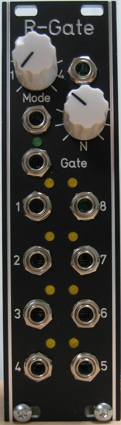
Rotating Gate: Front view
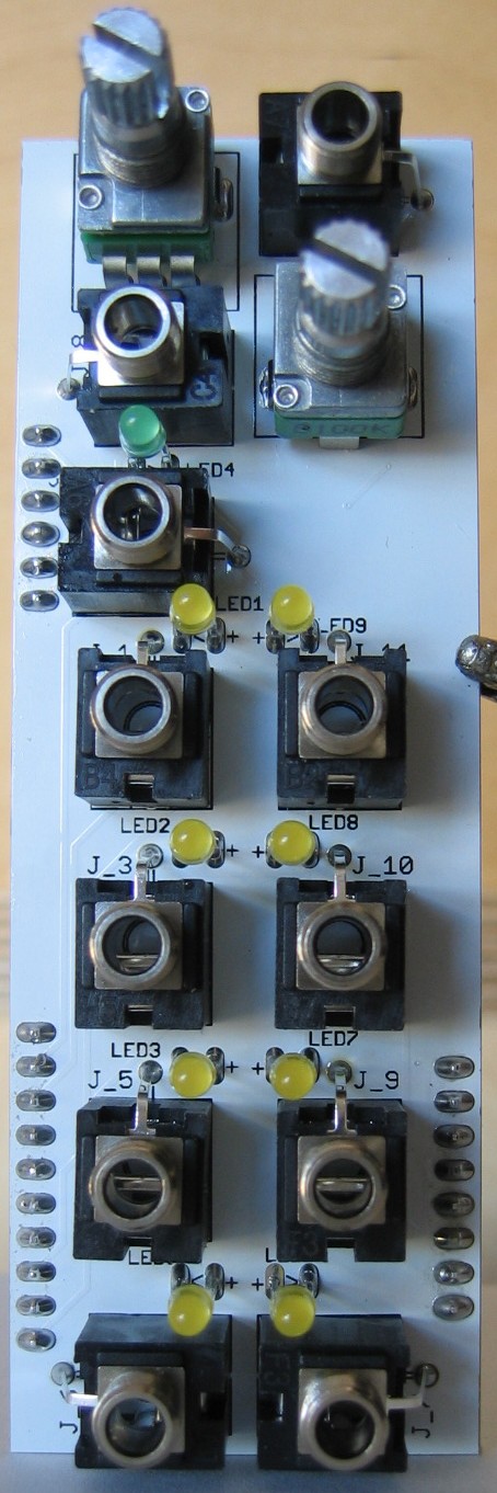
Rotating Gate: Populated control PCB top
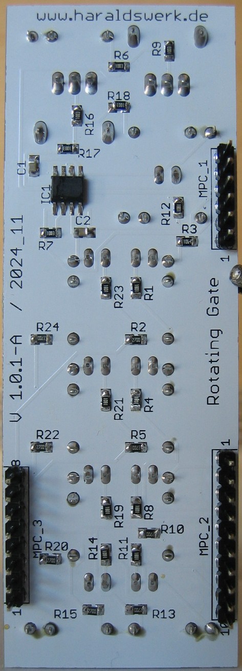
Rotating Gate: Populated control PCB back
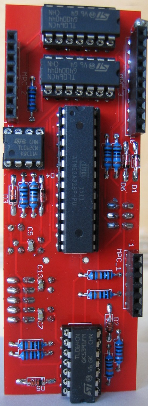
Rotating Gate: Populated main PCB top

Rotating Gate: Populated main PCB back

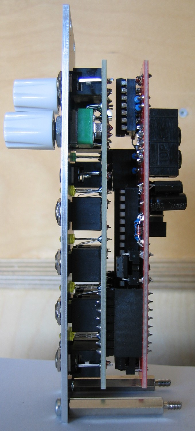
Rotating Gate: Halve front view

Rotating Gate: Halve back view