Motivation
Here is the add on board for my Moog Ladder Filter. It consist off three output stages similar to the one on the main board with the correction for gain loss when increasing the emphasis / feedback. All filter poles are brought out. This means additional 6dB, 12dB and 18dB outputs besides the the 24dB output from the main board. There was one OTA left so i added a simple VCA to use it. And a level indicator to give you some orientation about the signal.
Specs and features
- 6db, 12dB and 18dB brought out with this additional board
- Gain loss compensation when emphasis is turned up. Adjustable
- Additional VCA
- Signal indicator
- Schematic
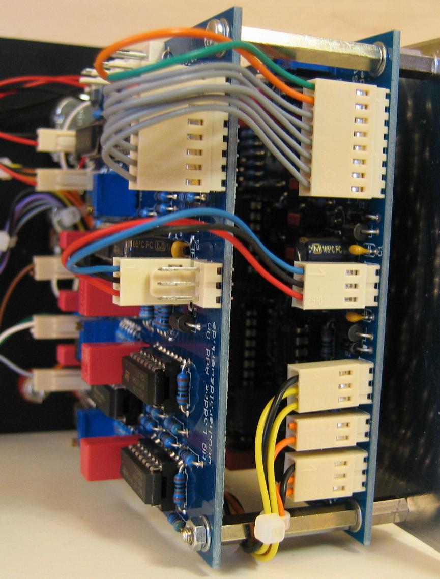
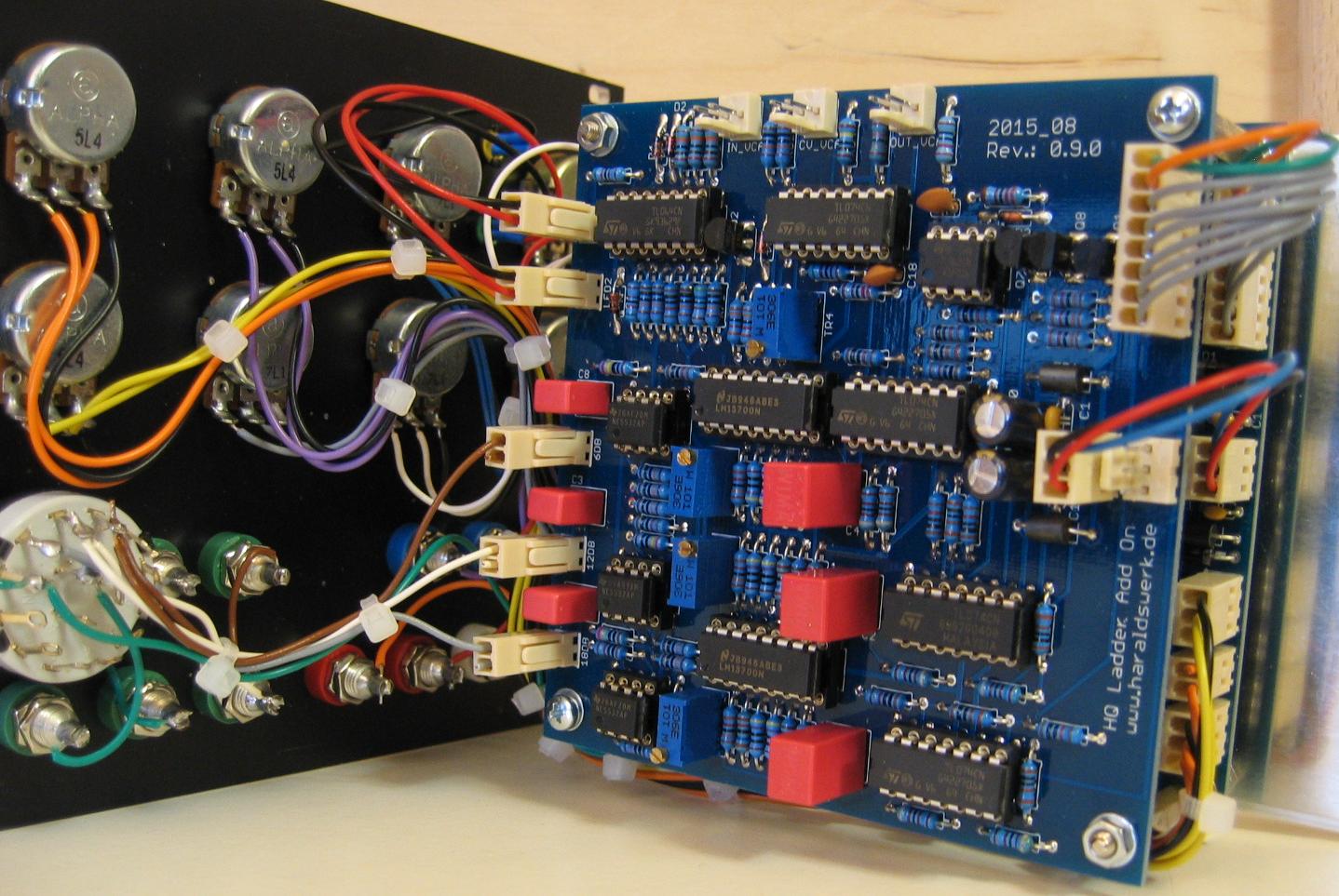
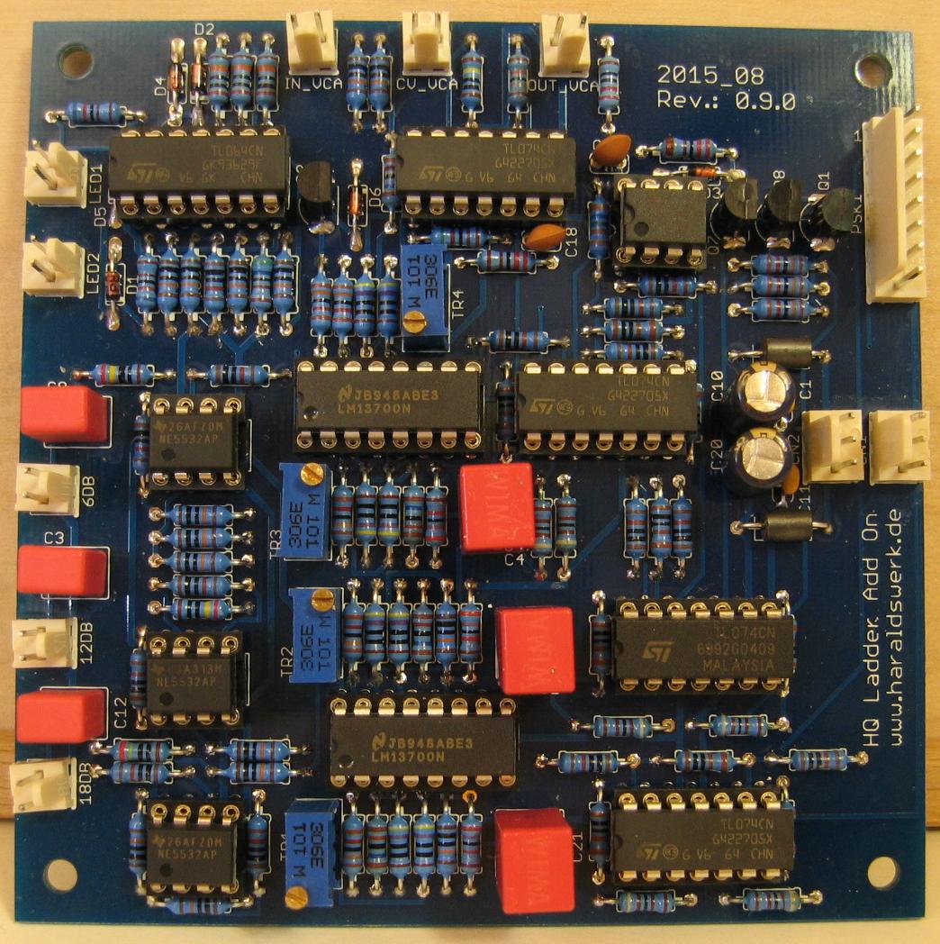
- Pictures
- Works on PSU with +12V/-12V or +15V/-15V as well
Implementation
Schematic
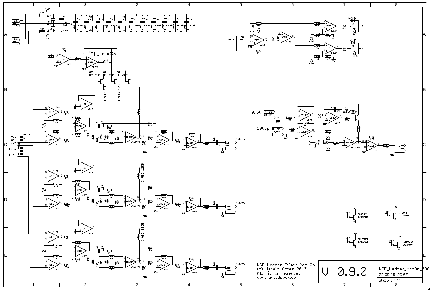
Moog Ladder AddOn schematic
Description:
The schematic follows the same principle as in the basic Moog Ladder board. The control voltage for the emphasis is used to control the gain of one half LM13700 OTA. The output of this OTA is added to the 6dB, 12dB or 18dB ladder output to compensate for the gain loss with high emphasis. The added amount is adjustable by changing one resistor.
TopCalibration
- OTA DC offset 6dB output: Ground the input of the OTA, where C4 and R50/R57 met. Set the feedback potentiometer to maximum. Measure the output voltage at pin5 of IC4 (LM13700). Adjust TR3 to zero volts. Remove ground.
- Gain loss compensation: Choose R55 to your needs. 30k is a good start. Or replace R55 with a trimmer or potentiometer.
- Same procdure for 12dB and 18dB output.
Special parts
None
12V Operation
The filter works at 12V as well as with 15V. However the performance at 12V can be optimized by changing a few resistors.
- R53, R34, R18 and R63 from 13k to 11k (Diode bias current for LM13700).
- R61, R42, R2 and RR76 from 13k to 10k (I_abc for LM13700).