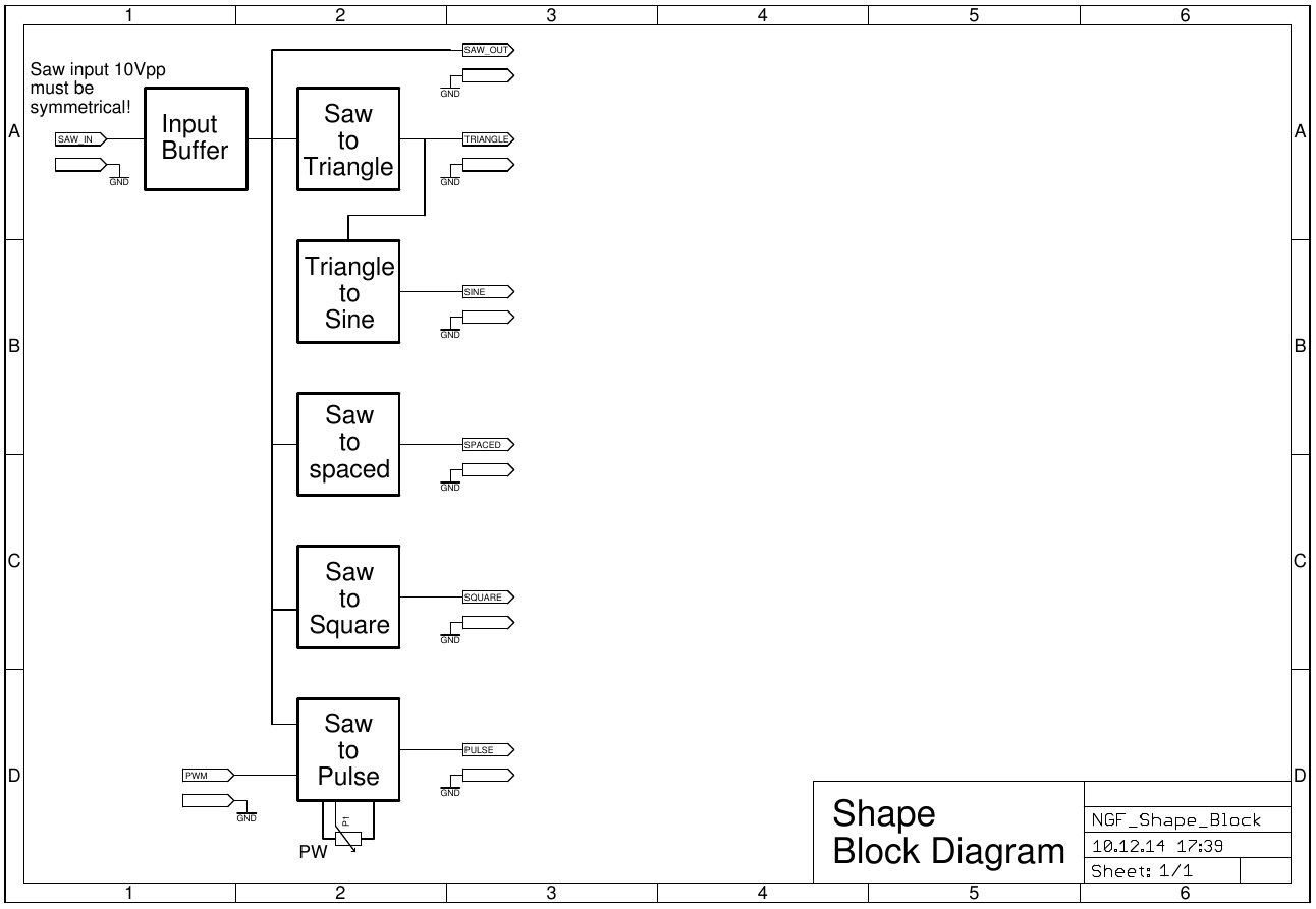
Motivation
I kept all the waveforms of the original Elektor Formant, but changed the circuitry significantly. The only thing i added a symmetrical square out, that i found useful for sync. For converting the saw wave to triangle a precision full wave rectifier is used, followed by a level shifter. The originally used matched Germanium diodes are hard to obtain these days. Here you only have to match two resistors. The switching glitch is not audible and can be suppressed with means of a capacitor of some 100pF if wanted. Don't choose the capacitance to high, it rounds the edge of the triangle.
For triangle to sine conversion i used a well known circuit that works better then the two diodes approach from the original. This circuitry can be found at various places in Electronotes and others. The circuitry is very sensible to the used values and input voltage. If you use another input voltage you probably have to change type of FET and resistor values.
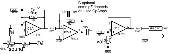
For wave shaping from saw to spaced saw I kept the original circuitry from the Elektor Formant. I only have to change some part values due to the different signal level.
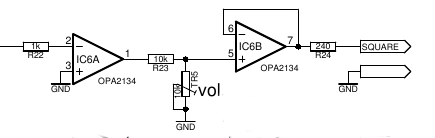
New added is the saw to square waveshaper because I found it usefull to have a symmetrical square output.
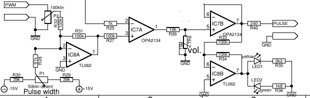
The saw to pulse shaping is quite different to the original but quite standard.
Specs and features
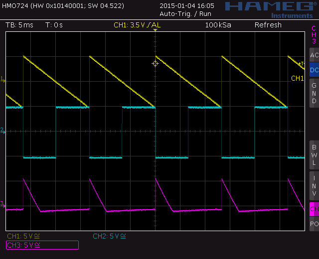
- Regular input: Symmetric saw 10Vpp. Other input can make some interesting sounds as well.
- DC coupled
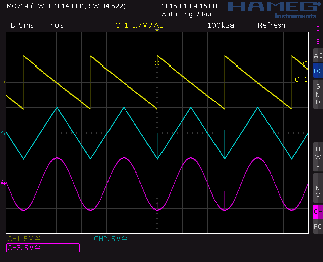
- Saw to triangle
- Triangle to sine
- Saw to square
- Saw to pulse
- Saw to spaced saw
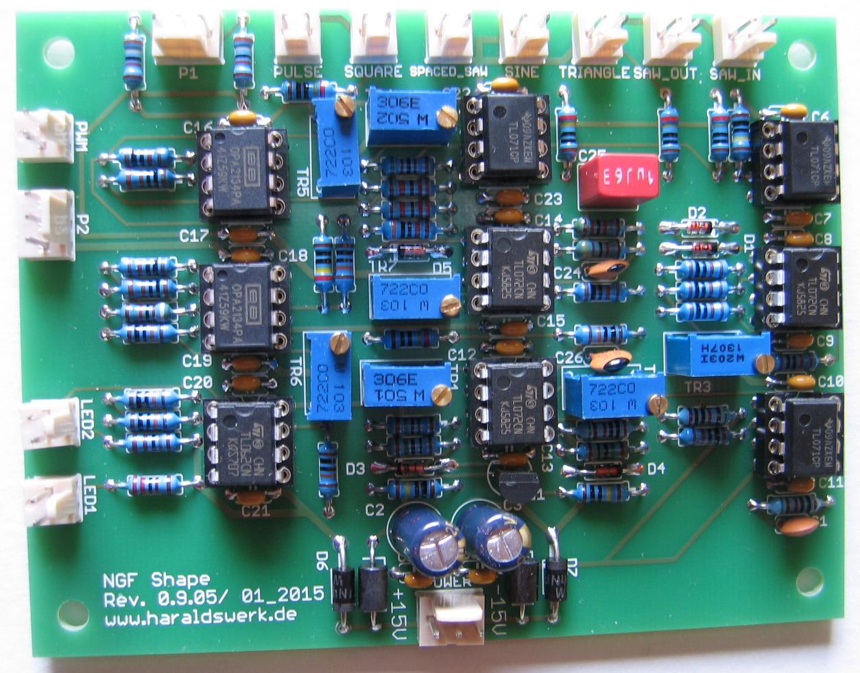
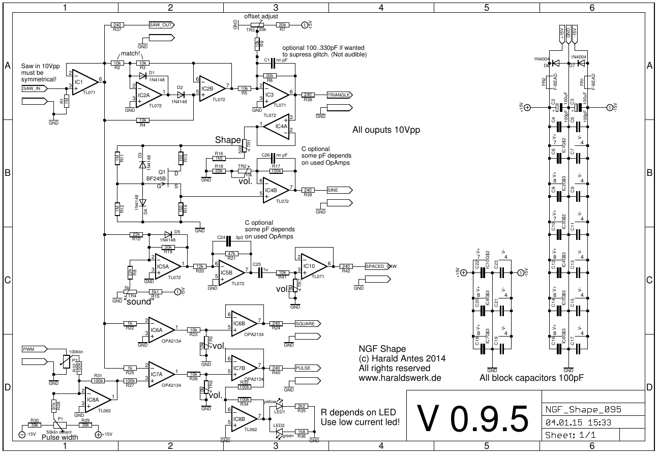
- Schematic
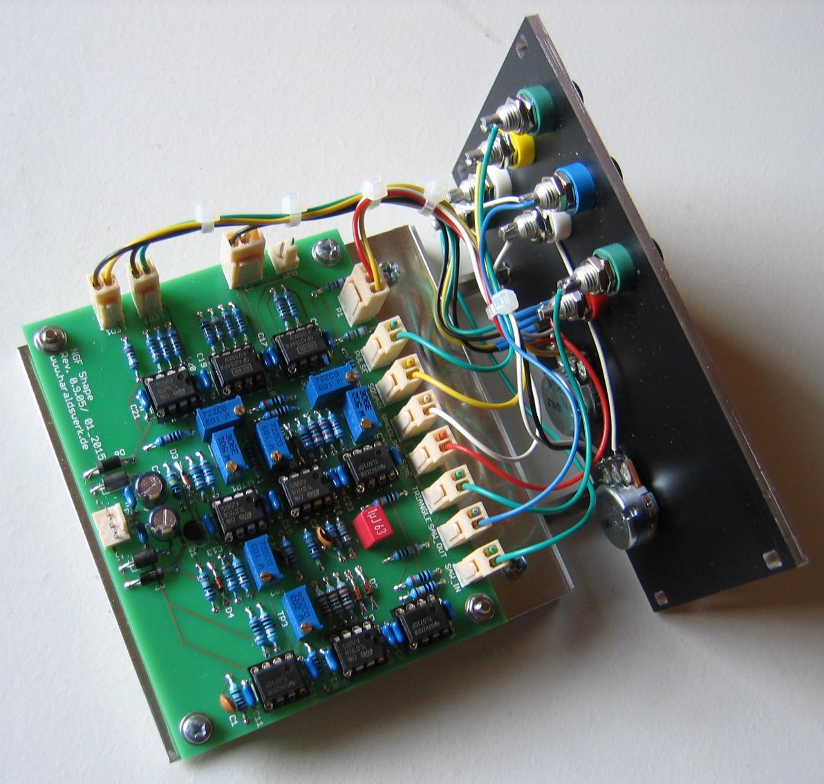
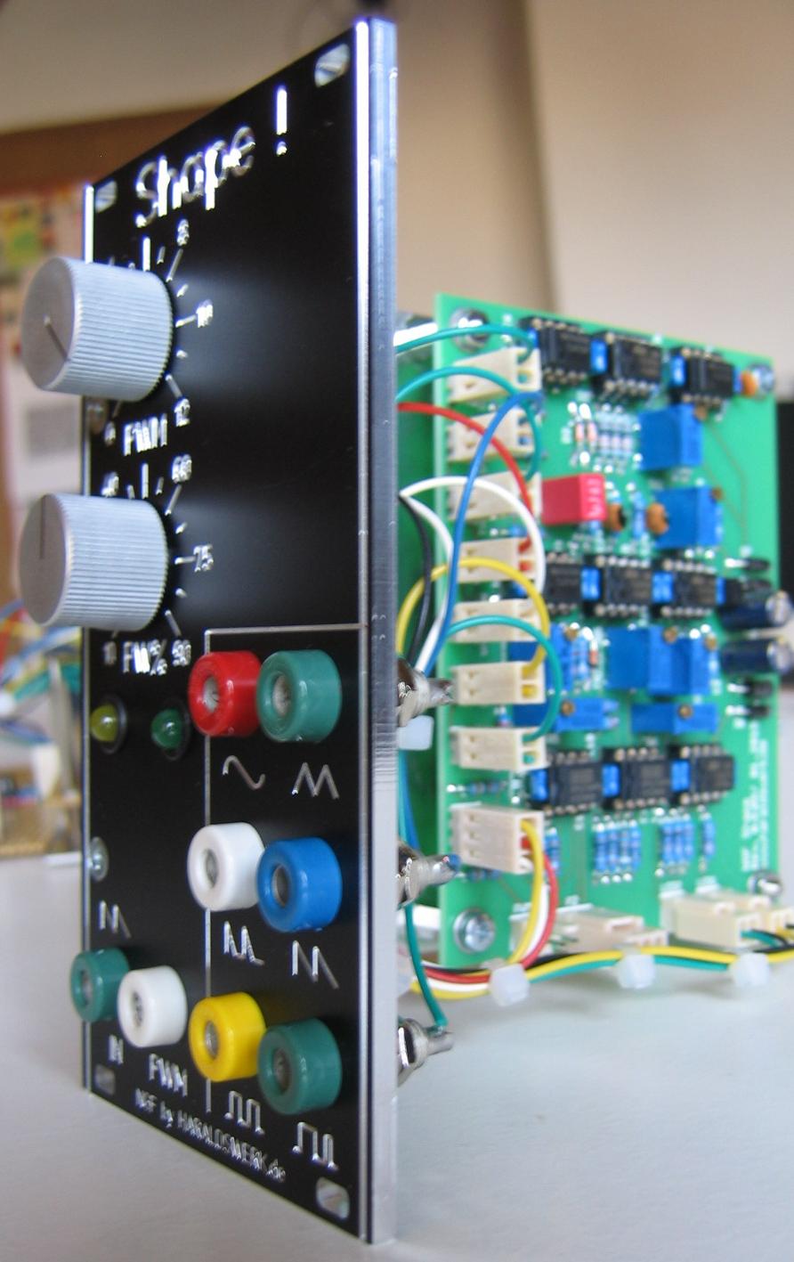
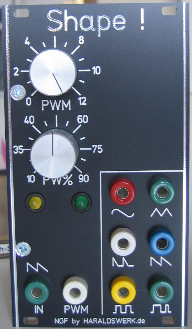
- Pictures
- PSU +15V/-15V xxmA/xxmA
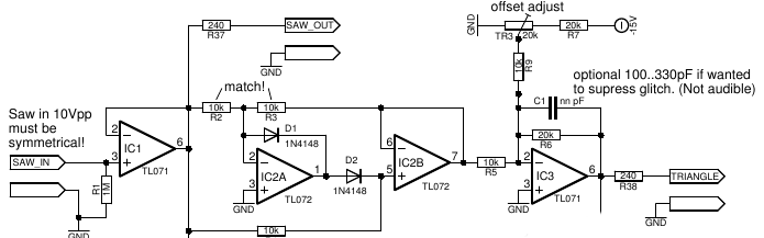
Saw to triangle
The saw to triangle conversion is done with means of a precision full wave rectifier with offset adjust. This avoids the problem of finding some matched diodes as used in the original Elektor Formant circuitry. The input of a symmetrical saw is a must for best performance!
Excerpt from the schematic:
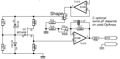
Triangle to sine
This circuit can be found at various places. The result is better as in the original two diodes approach in the Elektor Formant. But the components and their values must be chosen carefully.
Excerpt from the schematic:
Implementation
Calibration
- Set input to symmetrical saw! -5V..+5V!
- Adjust TR3 to zero DC offset for triangle
- Adjust TR1 for best sine shape. Adjust TR2 for sine volume.
- Adjust TR4 for "best" sound of spaced saw. Depends on your preference. Adjust TR7 for spaced saw volume.
- Adjust TR5 for square volume.
- Adjust TR6 for pulse volume
Special parts
None