Motivation
This module was originally build for my Shakuhachi to Synth project to provide the start/stop pulse for the Pitch to voltage converter. But it turned out to be much more useful. When you have the basics for your synthesizer like VCO, VCF, VCA, ADSR, LFO,... and some controllers and you want more, then using your keyboard to steer the synthesizer it is time for some modules to produce trigger signals out of different sources. Here is one of them. A signal to trigger converter. You can feed in a changing signal and every time the signal went through zero a trigger is generated dependent on the direction from where the zero point is crossed. You can add a threshold manually or CV controlled to move the zero point up or down as well. You can feed the signal in through input one ore two. When both inputs are used the signals are added together. When the signal crosses zero from positive to negative a trigger of about 0.1msec is generated at output -Trig. When the signal crosses zero from negative to positive a trigger of about 0.1msec is generated at output +Trig. Output +/-Trig provides both triggers. This output can be used to generate interesting rhythmic patterns when the threshold is set by a slowly moving CV or some DC offset is applied to the signal.
Specs and features
- Two added inputs
- Threshold manually and with CV
- Output for +Trig, -Trig and +/-Trig: 0.1msec
- Runs on +/-15V and +/-12V with minor resistor changes
- Power consumption below 25mA each rail
Implementation
Schematic

Signal to Trigger converter schematic: Control board

Signal to Trigger converter schematic: Main board
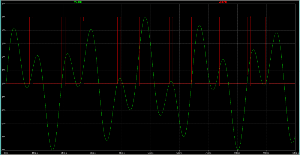
Example: Summed signal to trigger
Description:
The incoming signals are summed up. Every time when the summed signal changes polarity (moving through zero) a trigger is generated. Moving from plus to minus generates a trigger at the negative trigger output, moving from minus to plus generates a trigger at the positive trigger output. Trigger length is about 0.1msec.
The input signals are summed up with IC2C. The threshold and the threshold CV is summed up with IC2A (IC2B).If the sum from the input signal is above the threshold level at IC1A (IC1C) the output of the comparator IC1A (IC1C) went low. C1 (C2) is charged and differentiates the signal. R5 and R7 (R10, R8) builds a voltage divider which feeds the comparator IC1B (IC1D). D2 clamps the negative pulse to ground (D3 for positive). This is needed to make sure that the next positive (negative) charging pulse starts from zero load in the capacitor. Otherwise the output trigger length will vary with input frequency. R5(R10) and R7(R8) build the unload path for C1(C2). C1(C2), R5(R10) and R7(R8) determines the output trigger length. The comparator IC2C went high when the positive input reaches 6V. The output voltage is divided down by R4(R11) and R6(R12). D1(D4) blocks the negative voltage when the comparator switches back to the negative rail. R4(R21) scales the remaining voltage to 5V. IC1A(IC1C) serves as an output buffer. IC1B sums the negative and the positive trigger. IC1D is the output buffer for the +/-trigger output.
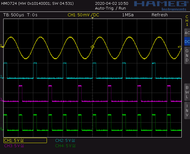
Screenshot: Sine to Trigger
The uppermost line (Yellow) shows the input signal. The second line (Blue) shows the trigger when the input signal moves to the positive site. The third line (Purple) shows the trigger when the input signal moves to the negative site. On the fourth line (Green) you can see both triggers added. This picture is taken without any threshold.
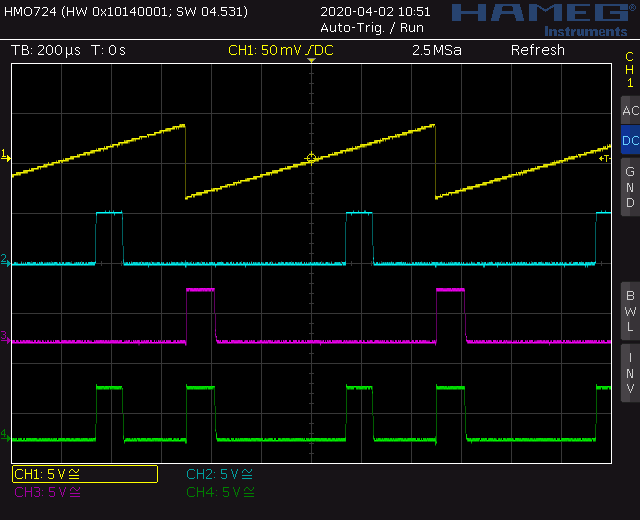
Screenshot: Saw to Trigger with threshold
The uppermost line (Yellow) shows the input signal. The second line (Blue) shows the trigger when the input signal moves to the positive site. The third line (Purple) shows the trigger when the input signal moves to the negative site. On the fourth line (Green) you can see both triggers added. Here you can easily see what is the threshold fore.
TopCalibration
- Set the threshold pots to center position
- Measure the voltage at pin14 of IC2A (pin8 of IC2B)
- Adjust trimmer TR1(TR2) to zero volt.
Building hints
- None
Special parts
- None
Download
Signal to Trigger converter main board documentation downloadSignal to Trigger converter main board Gerber files download
Signal to Trigger converter control board documentation download
Signal to Trigger converter control board Gerber files download
Signal to Trigger converter faceplate *.fpd file download
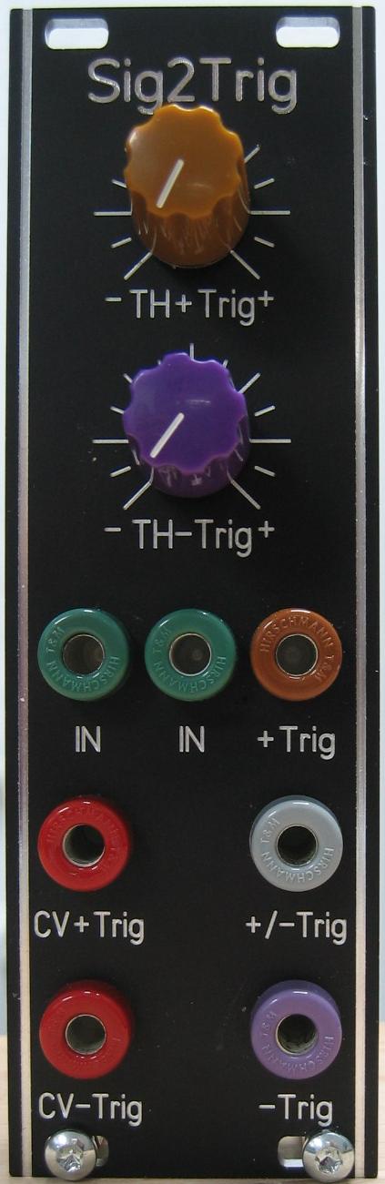
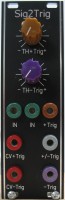
Signal to Trigger converter: Front view
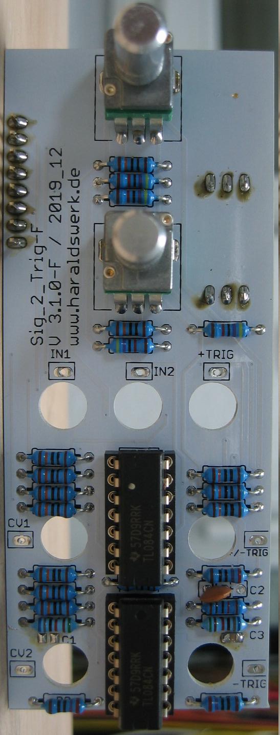
Signal to Trigger converter: Populated control PCB
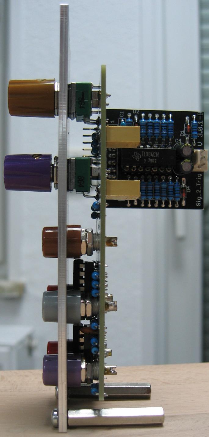
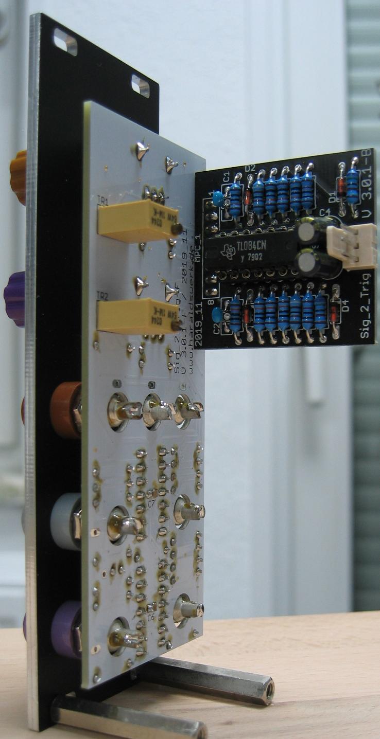
Signal to Trigger converter: Side view